Data Center Backup Power: Tier III/IV Requirements, Sizing & Redundancy [2026]
The cloud provider in Northern Virginia prepared to execute a 2.3 million dollar enterprise contract termination during March 2024. The final step required a Tier III witness test which an Uptime Institute certified engineer needs to conduct. The facility operated through an N+1 generator system which included three generators of 2,000 kW capacity. The test required normal operation with one unit deliberately taken offline. The third generator failed to synchronize when the control signal activated the parallel switchgear. The system experienced voltage fluctuations. The system activated the load shedding mechanism. The facility experienced a blackout that lasted for 11 seconds. The operators spent 2.3 million dollar enterprise contract The final step required a Tier III witness test which an Uptime Institute certified engineer needs to conduct. The facility operated through an N+1 generator system which included three generators of 2,000 kW capacity. The test required normal operation with one unit deliberately taken offline. The third generator failed to synchronize when the control signal activated the parallel switchgear. The system experienced voltage fluctuations. The system activated the load shedding mechanism. The facility experienced a blackout that lasted for 11 seconds. The operators spent 180000 dollars to rebuild the switchgear commissioning process from its beginning.
The failure could have been entirely avoided. You already understand that data center backup power represents the most expensive and challenging system requirements which your data center needs when you design build or operate data centers. A single error in redundancy math generator sizing or switchgear integration can cost millions in lost revenue SLA penalties or redesign.
The guide explains the actual requirements for data center backup power. The study will examine Uptime Institute Tier classifications N+1 versus 2N redundancy through actual calculations and PUE-based generator sizing together with UPS and ATS integration fuel strategy and maintenance discipline which ensures mission-critical plants remain operational.
Want the complete emergency power picture first? (Read our complete guide to emergency power systems before diving into data center specifics.)
What Is Data Center Backup Power?
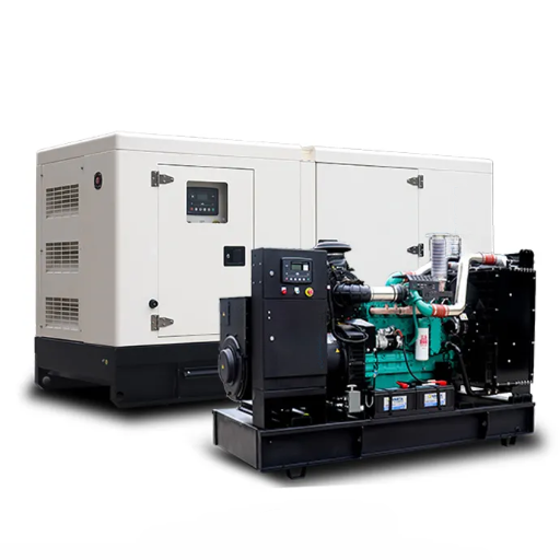
Data centers require backup power systems that extend beyond parking lot diesel generators. The backup power system functions as a specialized electrical system which ensures continuous operation of all IT equipment during power outages. The system must meet strict availability targets defined by the Uptime Institute Tier classification system.
The complete power chain starts from utility power which connects to an automatic transfer switch (ATS) that directs power to an uninterruptible power supply (UPS) which then distributes power through power distribution units (PDUs) to all the servers and storage systems and networking equipment. The data center backup power system uses multiple synchronized diesel generators which operate as the backup power source when utility power fails. The UPS provides power for 10 to 40 seconds until the generators reach operational status and take on the complete electrical load of the facility.
Facilities which fall under Tier III and Tier IV standards require standby-rated generators for their operations. The Uptime Institute requires a continuous or prime power rating with no runtime limitation. The generators need to operate at full capacity during power failures for an unlimited duration. Our emergency generator guide contains detailed information about emergency generator ratings which provide more technical specifications.
Uptime Institute Tier Requirements for Backup Power
The Uptime Institute Tier Standard establishes four levels of data center availability. Each tier imposes specific requirements on the backup power architecture.
Tier I and Tier II (N and N+1 Partial)
Tier I facilities lack all forms of backup systems. The backup power system provides complete power capacity which matches the electrical requirements of the facility. Tier II provides partial backup systems because some components include spare parts while other parts do not. The two tiers enable small colocation facilities and nonessential business data centers to operate with minimal operational interruptions.
Tier III (N+1 Concurrently Maintainable)
The Tier III level establishes backup power requirements for essential data center operations. The electrical system needs to have all its parts accessible for maintenance work which should not interfere with the IT systems. The generator plant requires that its facility operates at maximum capacity even when one generator unit is out of service.
The Tier III standard needs power sources which have prime power (PRP) and continuous power (COP) ratings. Standby-rated generators which are restricted to emergency operational use only do not meet the standard. The ISO 8528-1 Continuous (COP) rating is the only rating that unconditionally satisfies the no-runtime-limitation requirement for Tier III and Tier IV certification according to Cummins.
Tier IV (2N or 2(N+1) Fault Tolerant)
Tier IV represents the highest level of operational standards. The entire system design needs to operate without any points that could potentially cause failure. The generator plant uses a 2N or 2(N+1) design because it requires two separate power plants that can each handle the entire facility load.
Availability Targets:
| Tier | Redundancy | Uptime | Annual Downtime |
|---|---|---|---|
| Tier I | N | 99.671% | ~28.8 hours |
| Tier II | N+1 partial | 99.741% | ~22 hours |
| Tier III | N+1 full | 99.982% | ~1.6 hours |
| Tier IV | 2N/2(N+1) | 99.995% | ~26.3 minutes |
These numbers are not marketing goals. They are contractual SLA commitments that directly affect revenue and customer trust.
N+1 vs 2N Redundancy Explained
Redundancy is where most data center backup power designs succeed or fail. The terminology sounds simple, but the engineering implications are profound.
Defining “N”
In data center engineering, N equals the minimum capacity required to support the total facility load at full power. If your data center requires 4,000 kW of continuous power, then N = 4,000 kW. N is not the number of generators. It is the total capacity needed.
N+1 Redundancy
N+1 means one spare unit beyond the minimum required. A standard Tier III N+1 design uses three 2,000 kW generators when N reaches 4,000 kW. Two units carry the full load (N), and the third is the “+1” spare. The three units operate together during regular use with isochronous load sharing, which makes the units function at approximately 67 percent of their maximum capacity. The system operates with reduced power to enhance fuel efficiency while maintaining extra capacity for potential equipment failure.
2N Redundancy
2N means two completely independent, mirrored power systems. For the same 4,000 kW load, a Tier IV design might have System A with three 2,000 kW generators (N+1) and an entirely separate System B with its own three 2,000 kW generators (N+1). Either plant can carry the full 4,000 kW load independently. No single generator failure, switchgear fault, or fuel system blockage can take the facility down.
Common N+1 Mistakes
A colocation facility in Denver discovered one of these mistakes the hard way in 2022. The engineering team sized their N+1 plant based on IT load alone, ignoring the Power Usage Effectiveness (PUE) factor. The generator voltage dropped by 22% when utility power failed because all CRAC units tried to restart at the same time. The protective relay tripped offline. The UPS batteries completely ran out of power. The data center experienced a total outage. The remediation required a 40% larger generator plant and $85,000 in electrical upgrades.
The use of one oversized monolithic generator instead of multiple units in parallel and the failure to account for future growth create common errors which result in an N+1 system becoming an N system within three years.
How to Size Data Center Backup Power
Sizing a data center generator plant is more complex than adding up server nameplates. The calculation must account for cooling, power conversion losses, future growth, redundancy, and environmental derating.
Step 1: Calculate the Critical IT Load
Start by summing the power draw of all IT equipment: servers, storage arrays, network switches, and firewalls. For example, a medium-sized facility might have 500 servers averaging 400 W each, plus storage and networking, yielding an IT load of approximately 2,000 kW.
Step 2: Apply PUE (Power Usage Effectiveness)
PUE is the ratio of total facility power to IT power. It accounts for cooling (CRAC units, chillers, pumps), mechanical systems, lighting, and power conversion losses. A highly efficient hyperscale facility achieves a PUE of approximately 1.2. An average colocation facility runs closer to 1.5.
Total Facility Load = IT Load × PUE
Using our example: 2,000 kW IT load × 1.35 PUE = 2,700 kW total facility load. Cooling and mechanical infrastructure alone added 700 kW. Ignoring this is the most common sizing mistake in the industry.
Step 3: Add a Growth and Safety Margin
Data centers grow. Always add a 20-25% margin above the current calculated load. Furthermore, generators operate most efficiently and safely between 70% and 80% of their rated capacity. If you size the plant too tightly, you lose redundancy headroom and fuel efficiency.
Using our example with 25% growth: 2,700 kW × 1.25 = 3,375 kW.
Step 4: Apply the Redundancy Configuration
- Tier III (N+1): Size N for the buffered load, then add one identical unit.
- Tier IV (2N): Size two independent plants, each capable of the full buffered load.
Step 5: Account for Environmental Derating
A generator rated at sea level will not deliver the same output in hot, high-altitude conditions.
- Altitude derating: Capacity drops approximately 3.5% per 1,000 ft above sea level.
- Temperature derating: Capacity drops approximately 1% per 10°F above 77°F.
At 3,000 ft elevation, a generator loses roughly 10.5% of its nameplate rating.
Worked Example:
- IT load: 2,000 kW
- PUE 1.35 → Total facility load: 2,700 kW
- 25% growth margin → 3,375 kW
- Altitude derating at 3,000 ft (10.5%): 3,375 ÷ 0.895 = 3,771 kW minimum
- Tier III N+1 → three 1,500 kW generators in parallel (4,500 kW total)
- Tier IV 2N → two independent plants of three 1,500 kW generators each
This systematic methodology prevents the failures that occur when plants are sized on IT load assumptions alone.
UPS, ATS, and Generator Integration
Generators do not start instantly. The UPS and ATS are what make the transition seamless.
The UPS Bridge
The UPS system maintains uninterrupted power to the IT equipment when utility power sources experience failure. The UPS system requires sufficient battery power to maintain operations until generators achieve voltage and frequency stabilization through the starting and synchronization process. The time period between engine start and engine air system activation and temperature conditions determines the duration which usually lasts between 10 and 40 seconds.
The generator plant needs to meet the maximum power requirements which occur when UPS batteries need recharging. The UPS systems require high power consumption after extended power failures to restore their battery capacity. A Miami data center experienced this problem in 2017 when their generator system failed after 18 minutes of hurricane power outage because the UPS recharge load had never been included in the sizing study.
Automatic Transfer Switch (ATS)
The ATS detects utility loss and transfers the facility load to the generator plant. For critical facilities, specify a bypass isolation switch so maintenance can be performed without interrupting power. For more details, see our generator transfer switch guide.
Paralleling Switchgear
Paralleling switchgear is essential for any N+1 or 2N design. It allows multiple generators to synchronize and function as a single power source. Isochronous load sharing distributes the electrical load evenly across all running units, preventing any single generator from being overloaded while others idle.
Fuel Systems and Runtime Strategy
A perfectly sized generator plant is useless if it runs out of fuel or cannot start because of contaminated diesel.
Diesel Dominance
Diesel remains the dominant fuel for data center backup power. It offers rapid cold-start capability, high motor-starting torque for chillers and pumps, and independence from utility pipelines that can fail during earthquakes or cyberattacks. Natural gas and hybrid systems are gaining adoption for sustainability targets, but diesel is still the engineering standard for Tier III/IV uptime.
Fuel Storage Requirements
Tier III data centers are generally expected to maintain at least 72 hours of on-site fuel storage for extended outages. NFPA 110 adds a 133% safety buffer to calculated consumption, accounting for incomplete combustion, load fluctuations, and the inability to refuel during widespread disasters.
Calculation example:
- Generator burn rate at full load: 80 gallons/hour
- Basic 72-hour need: 80 × 72 = 5,760 gallons
- With 133% NFPA 110 buffer: 5,760 × 1.33 = 7,661 gallons minimum
Day Tank vs Main Tank
Large data center generator plants typically use a two-tank fuel system:
- Main storage tank: Holds bulk fuel underground or aboveground. Must account for unusable bottom volume, typically 10%.
- Day tank: Located near each generator, holds 4-8 hours of fuel directly supplying the engine.
- Transfer pumps: Automatically refill the day tank from main storage under level control.
Testing and Maintenance Best Practices
An untested generator plant is a liability. Generators account for approximately 28% of data center outages. Preventive maintenance and rigorous load testing are non-negotiable.
Weekly Visual Inspections
Every week, a qualified technician must inspect:
- Fuel level, leaks, and water contamination
- Engine oil level and condition
- Coolant level and freeze protection
- Battery electrolyte, terminals, and charger status
- Control panel indicators and fault codes
- Paralleling switchgear synchronization settings
Monthly Loaded Testing
NFPA 110 requires a minimum 30-minute loaded test every month. The generator must achieve at least 30% of its nameplate kW rating or the manufacturer’s minimum exhaust gas temperature. The Wet stacking condition occurs when equipment operates below 30% load because it leads to carbon deposits and unburned fuel accumulation in the exhaust system which reduces efficiency by 15-25% and results in permanent engine damage.
A hyperscale campus in Ohio skipped annual load bank testing for two consecutive years because “the monthly no-load runs looked fine.” The generators experienced carbon deposit overload after a winter storm caused a 14-hour power outage which resulted in a complete engine rebuild within three hours. The repair bill: 47,000. TheSLApenaltiesfromcustomers:47,000. TheSLApenaltiesfromcustomers:220,000.
Annual and Triennial Testing
Under the 2025 NFPA 110 edition, the annual load bank test protocol requires:
- 50% of nameplate kW for 30 minutes
- 75% of nameplate kW for 60 minutes
- Total: 1.5 continuous hours
Every 36 months, Level 1 systems must undergo a 4-hour continuous test at actual building load or 30% of nameplate, whichever is greater. This extended duration reveals problems that short tests miss: fuel pump starvation, sustained-load overheating, and switchgear drift.
For a full breakdown of testing schedules, see our NFPA 110 compliance guide.
Battery Maintenance
Approximately 80% of generator starting failures are battery-related. Best practice calls for weekly inspections, monthly impedance or conductance testing, and replacement every 3-5 years.
ZC Power Data Center Backup Power Solutions
As a source manufacturer with a 300,000-square-meter facility and national standard testing center, ZC Power builds data center backup power systems that meet the most demanding global Tier III and Tier IV standards.
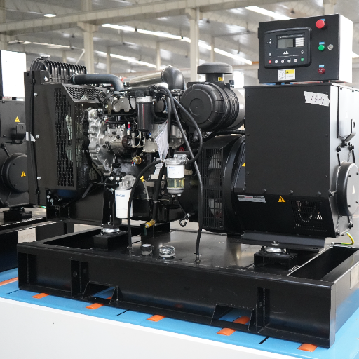
Factory-Built Tier III/IV Generator Plants:
- Engineered for N+1 and 2N redundancy with full paralleling switchgear
- Pre-wired and factory-acceptance tested before shipment
- Load tested at 110% of rated capacity in our national standard testing center
Containerized Modular Power Stations:
- 20ft and 40ft CSC-certified containers for rapid hyperscale and edge deployment
- Pre-wired switchgear and controllers reduce field commissioning to under 10 days
- Weather-resistant steel frames with anti-corrosion powder coating
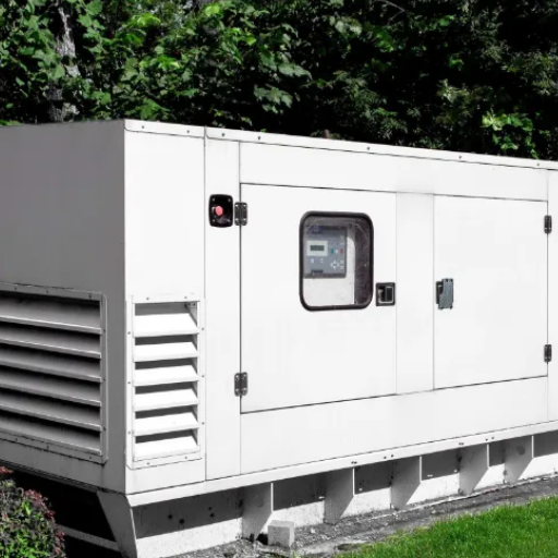
Silent Canopies for Urban and Edge Data Centers:
- Sound-attenuated enclosures keeping noise below 75 dB at 7 meters
- Maintain full airflow and cooling performance
- Ideal for edge facilities in dense urban environments with strict noise ordinances
For more details on acoustic solutions, explore our silent generators for urban data center campuses.
Custom Engineering and Global Compliance:
- Configurations from 8kVA to 4000kVA
- Custom voltage and frequency for international grid requirements (50Hz and 60Hz)
- ISO9001, CE, and CCC certified
- OEM and ODM capabilities for data center infrastructure distributors
Global Support:
- 80+ technical engineers
- Commissioning, startup assistance, and training
- Direct OEM parts supply to data centers worldwide
Frequently Asked Questions
What is N+1 redundancy in a data center?
N+1 redundancy means there is one spare backup component (such as a generator) beyond the minimum number required to support the full facility load. If any single unit fails or is taken offline for maintenance, the remaining units can still carry 100% of the load.
How long must a data center generator run?
Tier III data centers typically maintain at least 72 hours of on-site fuel storage. The generators themselves must be rated for continuous or prime power, meaning they can run indefinitely at full load without runtime limitation.
What is PUE and why does it matter for generator sizing?
PUE (Power Usage Effectiveness) is the ratio of total facility power to IT power. It matters because cooling and mechanical systems can add 30-50% to the total electrical load. A generator plant sized only for IT load will be dangerously undersized.
How fast must a data center generator start?
Data center generators typically must start, synchronize, and assume the full load within 10 to 40 seconds of utility failure. The UPS batteries bridge this gap to prevent any interruption to IT equipment.
Can a data center use natural gas generators?
While natural gas is technically possible and is growing in adoption for sustainability reasons, diesel remains the industry standard for Tier III/IV data center backup power because it offers faster startup, higher motor-starting torque, and independence from utility pipelines.
Conclusion
Data center backup power is not a commodity purchase. It is a long-term infrastructure investment that spans electrical engineering, redundancy architecture, regulatory compliance, and decades of operational discipline.
Key takeaways:
- Match your Tier requirement to the right redundancy model (N+1 for Tier III, 2N for Tier IV)
- Size generators using PUE-based total facility load, not just IT load
- Integrate UPS and paralleling switchgear seamlessly to bridge the startup gap
- Design fuel storage around the 72-hour rule with the 133% NFPA 110 buffer
- Maintain complete test logs and rigorous load bank testing schedules
- Choose a manufacturer with proven Tier III/IV experience and certified pre-shipment testing
ZC Power has dedicated its 25 years of existence to developing emergency power systems which function for crucial moments. The diesel generator plants we provide for data centers undergo testing at our national standard testing center which operates according to your specific redundancy and environmental system requirements. Our testing center operates with more than 80 technical engineers from around the world who support our customers.
For proper load bank testing procedures aligned with NFPA 110, (refer to our step-by-step testing guide.)