
Generator Paralleling Protection: Study Inputs and Setting Responsibilities
Generator paralleling protection starts with the actual machines, network and permitted operating modes. The study then needs an approved settings package that matches the installed devices. Assign responsibility for supplying data, calculating settings, approving changes and proving the trip paths before accepting the system.
Does a folder marked “protection complete” cover the plant you intend to operate? Use the registers below to check.
Key Takeaways
- Study the permitted source combinations, including reduced-source and maintenance conditions.
- Request exact alternator and excitation data; a generator power rating cannot replace fault-response curves.
- Identify sensing, protection zones and breaker trip paths separately from control functions.
- Assign design approval, settings implementation and test responsibilities explicitly.
- Match approved files to installed devices and retain the as-left records after testing.
Define the generator paralleling protection study boundary
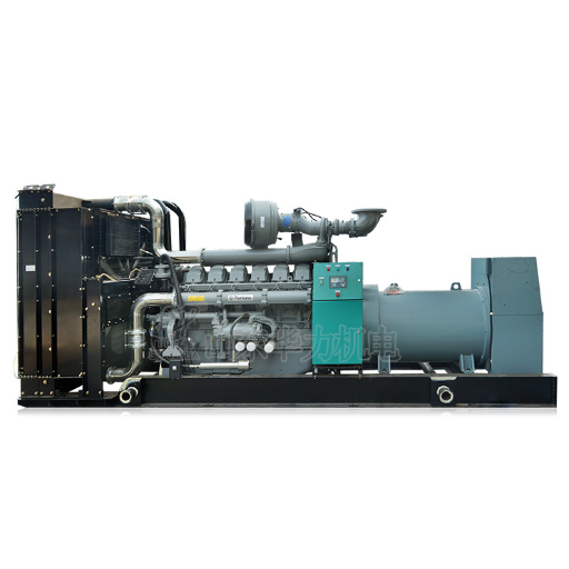
Record operating modes and source combinations
Start with the approved single-line diagram and a list of allowed operating modes. Identify generator incomers, bus sections, bus ties, transformers and the utility connection where present. Record other connected sources, including motors and inverter-based equipment, for the study engineer to assess.
An islanded bus and a utility-connected bus present different source conditions. The study must explain which combinations its conclusions cover. The Cummins paralleling application manual provides the wider system context; its examples are not settings for your plant.
Don’t reduce the mode list to “normal” and “emergency.” Include the permitted reduced-generator condition, maintenance tie positions and transfer states that affect the electrical network. Record prohibited combinations too, together with the control or physical arrangement intended to prevent them.
Illustrative scenario: A review package covers all generators connected, but the operating specification permits one set to supply a bus during maintenance. Leave that mode as an open study item until the appointed engineer assesses it. An approved drawing for the larger source combination does not close the missing case.
Bring the current single-line and mode list to your next review. Use the generator paralleling specification to keep protection requirements connected to the wider equipment and interface scope.
Distinguish controls from protection
Load management determines which loads or sets the plant intends to run. Protection detects defined abnormal conditions and initiates the specified response. Record their interfaces without treating a controller feature list as proof that the whole protection scheme is complete.
Reference each mode in calculations, setting groups and test records. Name the owner of any manual operating restriction.
Collect machine-specific inputs before the coordination study
Build an input register with named providers
A generator nameplate identifies rated output but does not describe the full fault-current response. Ask for data tied to the supplied alternator, excitation arrangement and operating basis. The study engineer should identify the parameters needed by the selected model and flag assumptions awaiting confirmation.
Use the following register as a review template. The proposed providers are discussion starting points; the project contract decides actual duties.
| Input group | Proposed provider | Review question | Closure record |
|---|---|---|---|
| Single-line and modes | Owner and electrical designer | Which source and tie combinations are permitted? | Drawing revision and approved mode list |
| Alternator and excitation | Generator supplier or OEM | Does the data match the supplied machine and excitation? | Model identity, curves and data revision |
| Network and sources | Designer and utility interface lead | Are relevant maximum and minimum source conditions included? | Network data, assumptions and utility correspondence |
| Breakers and sensing | Switchgear integrator | Are device curves, ratios and locations correct? | Device schedule and schematic references |
| Protection devices | Relay or controller supplier | Are firmware, options and setting units identified? | Device manual and configuration revision |
For the alternator, request applicable reactances, time constants and their stated bases. Identify rated voltage, frequency, winding connection and excitation type. Collect the manufacturer’s fault-decrement and thermal-damage information rather than substituting a curve from a similar catalog model.
Network inputs include cable type and length, transformer rating and impedance, and the connected-source data needed for the chosen calculation. Where utility paralleling is permitted, route utility contribution data and interconnection requirements through the designated interface lead. Do not assume export permission from the presence of a mains breaker.
Read decrement, damage and trip curves differently
A decrement curve describes how generator fault current changes with time under its stated conditions. A damage curve describes machine withstand limits. A breaker or relay characteristic describes device response. The coordination review needs these distinctions; placing three lines on one plot does not make them interchangeable.
STAMFORD AvK AGN035 explains overload and fault protection in relation to alternator characteristics. Use its method to frame questions about machine protection and clearing time. Its example values do not establish the pickup or delay for another alternator.
Request current-transformer (CT) and voltage-transformer (VT) ratios, accuracy information appropriate to the scheme, polarity and physical location. Include breaker opening information and the applicable trip-unit curves. A study based on a different CT ratio or device option needs an explicit disposition before implementation.
If documents disagree, don’t silently choose the newest-looking file. Record the conflicting identifiers and ask the responsible provider which information represents the supplied equipment. Mark provisional values as provisional in the study input register, with an owner and a date for resolution.
Synchronization sensing is another interface to document. Use the separate generator synchronization requirements guide for breaker-closing evidence; keep this article’s register focused on protection inputs and setting ownership.
Map protection functions to zones and trip paths
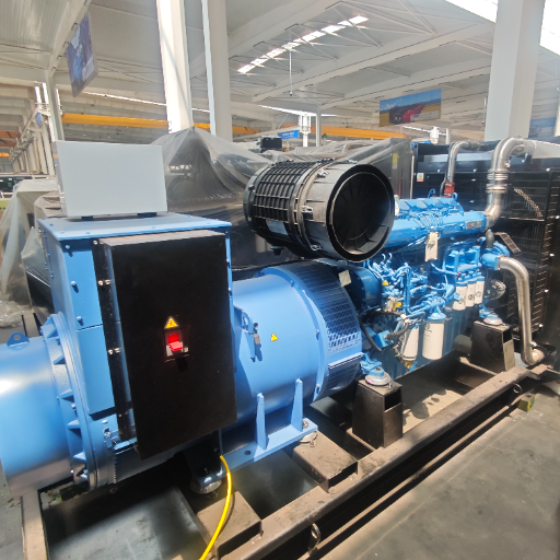
Explain what each function protects
The required functions depend on the machine, voltage level, grounding arrangement, network and operating duty. A manufacturer’s available-function list is useful for identifying questions, but it does not prove those functions are supplied, enabled or suitable for a particular project.
Overcurrent protection addresses defined current conditions, with characteristics selected against the system and machine behavior. Where used, voltage-dependent overcurrent schemes need their voltage-sensing basis documented too. Reverse-power protection concerns power flowing into a generator operating as a motor; its setting needs the relevant machine and prime-mover basis.
Differential protection compares currents at defined zone boundaries. Earth-fault protection depends on the grounding arrangement and sensing scheme. Voltage and frequency functions address their specified abnormal conditions. Sync-check supervises a closing permission where provided; it should not be treated as a substitute for the other protection functions.
For each applicable function, ask the study engineer to state the protected equipment, measurement location, operating condition and intended action. Avoid copying an entire relay catalog into the specification. An unused function should not appear in the acceptance register as installed protection.
Trace the signal through to physical response
Which breaker opens, through which path? Start at the CTs or VTs, follow the device input and logic, then identify the output contact, control-power source, trip circuit and breaker feedback. Record whether the response is an alarm, a breaker trip, an engine shutdown or a coordinated combination.
Separate the protection zone from the equipment’s commercial package boundary. A CT mounted in switchgear may provide a measurement used by a generator-mounted device. The drawing must identify both ends and the party responsible for the interface, including the documented response to loss of required sensing or control power.
A discrepancy in CT polarity markings belongs in the drawing and test review, not in an improvised setting change. Ask the integrator to reconcile the schematic, terminal identification and approved test method. Do not infer the correct wiring solely from an alarm label on the display.
The generator load-sharing guide explains the normal kW and kVAr control objective. Keep that operating objective separate from the protection action taken when a defined limit or abnormal condition is detected.
Use a trip matrix with columns for initiating function, device, operating mode, target breaker, engine action, reset permission and evidence reference. Where multiple devices can initiate the same trip, retain each initiating path. A common final output does not prove that every input path has been checked. Ask which initiating paths the test record actually covered before accepting a shared trip result.
Assign setting responsibilities and approval authority
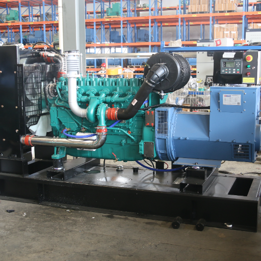
Put ownership beside each deliverable
Who can authorize a setting change after the factory acceptance test (FAT)? Agree on that authority before the equipment leaves the factory. “By others” is incomplete unless the named party accepts the deliverable, its input dependencies and its approval route.
The matrix below is a proposed project-management tool, not a universal contractual allocation. One organization may hold several roles, but the approval and implementation records should still distinguish them.
| Deliverable | Proposed responsible party | Required handoff |
|---|---|---|
| Design basis and operating modes | Owner’s appointed electrical designer | Approved scope and restrictions to study engineer |
| Machine-specific data | Generator OEM or supplier | Identified data set and outstanding assumptions |
| Protection study and proposed settings | Appointed protection engineer | Calculations, setting rationale and limitations |
| Design acceptance | Named project design authority | Approval or recorded comments and disposition |
| Utility interface acceptance, where applicable | Designated utility interface lead | Applicable requirements and acceptance records |
| Device configuration | Switchgear integrator or assigned implementer | Installed file and device/version identity |
| Testing and handover | Commissioning lead and owner representative | Test results, deviations and as-left records |
SEL’s protection engineering scope distinguishes scheme design, modeling, studies, settings and testing as separate activities. Use that distinction when comparing proposals. A quote covering device supply does not by itself establish who will calculate or approve the final settings.
Control changes after approval
Illustrative scenario: A controller export contains a default that differs from the approved setting sheet. The integrator can identify the discrepancy, but that does not automatically grant design authority to choose a replacement value. Record the difference, obtain the appointed approver’s disposition and retain the implementation and retest evidence.
Give each setting change a reason, requester, approver, affected device and effective revision. Record whether the change affects other devices, operating modes, drawings or test procedures. Preserve the previous approved file so the project can explain what changed and why.
For a mixed-fleet retrofit, clarify which supplier owns each machine’s input data and who reviews the combined plant. The paralleling dissimilar generators article covers the wider compatibility boundary; protection coordination still needs a single accountable study scope.
Complete the responsibility matrix with your project team before issuing a purchase or test package. Ask each proposed owner to confirm its deliverable and exclusions. If approval authority remains disputed, carry that dispute as an open project action rather than treating a commissioning witness’s signature as design approval.
Request a traceable setting and test evidence package
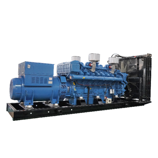
Connect calculations to the installed file
A study report and a settings export should be traceable to each other. Request the approved study revision, the relevant operating modes, device identity and setting-sheet reference. The setting record should state units and the applicable primary or secondary measurement basis so a reviewer can interpret the values correctly.
For each device, retain the configuration file, firmware identification and the approved protection logic where applicable. Record any setting group selection and the conditions under which it changes. A file named “final” is insufficient if its device identity or approval reference is missing.
Use a register that can remain open until each row has evidence:
| Function and device | Study reference | Approved setting record | Implementation evidence | Test and closure |
|---|---|---|---|---|
| Reverse power on the identified generator device | Relevant study section and source-mode reference | Approved pickup, delay, units and approver | Device export and version identity | Defined test scope, observed action and disposition |
| Overcurrent on the identified incomer device | Coordination plot and machine-withstand reference | Approved characteristic and setting-sheet revision | Installed trip-unit or relay configuration | Applicable test results and any required retest |
Ask the reviewer to explain any coordination limitations. The objective is an accepted design with stated assumptions and restrictions, not an unsupported promise of selectivity under every possible condition. A signed exceptions register is more useful than a blanket statement that every breaker is coordinated.
Separate the evidence provided by different tests
Injection testing, logic checks, trip-path checks and full system tests answer different questions. For each test, record:
- The signal or condition applied and its point of application.
- The device response, trip output and breaker action actually observed.
- The sensing, wiring or system behavior outside the test boundary.
A simulated relay input does not automatically demonstrate every element of the installed sensing circuit. Keep that limit visible beside the result.
A load-bank test can document performance within its stated load and test scope. It does not by itself prove fault coordination or every protection trip path. Likewise, an approved calculation does not demonstrate that the correct file was loaded into the installed device.
Coordinate the protection evidence package with the review of paralleling control failure modes. State how alarms, trips, loss of communications and recovery permissions interact in the approved design. Do not infer a universal trip response from the word “failsafe.”
Return to the missing maintenance mode in the earlier scenario. Closure needs the engineer’s assessment and its consequences for settings, operating restrictions or testing. A test report for a different mode cannot close that row just because both reports concern the same switchboard.
At handover, identify who retains the as-left backups and controls future changes. Keep unresolved deviations visible with a named owner and an agreed disposition route. Testing complete and documentation complete are separate statements; make clear which one the available records support.
Generator paralleling protection FAQ and project handoff
What data does a generator protection study need?
It needs the permitted operating modes, network configuration, machine-specific alternator and excitation data, connected-source information, device characteristics and sensing details. The appointed engineer determines the exact modeling inputs. Each input should identify its provider, revision and assumptions so the study can be checked against the equipment actually supplied.
Who approves reverse-power settings?
The project must name the design authority responsible for approving settings, with the relevant OEM and study-engineer inputs. Approval cannot be inferred from who operates the controller or witnesses a test. Use the machine and prime-mover requirements to establish the basis; do not substitute a universal percentage from another installation.
Is a controller default an approved setting?
A default is not project approval. Compare the installed value with the approved setting sheet, device options and firmware basis. If they differ, record the discrepancy and route it to the appointed authority. Retain the authorized change, implementation record and any required retest before closing the item.
Does a load-bank test prove protection coordination?
No. It demonstrates only the behavior observed within its defined load and test scope. Protection coordination needs an appropriate study, while installed protection also needs evidence for the specified sensing, logic and trip paths. Review these records together; do not use one load report to imply that untested fault responses passed.
When should changes return to the study engineer?
Return changes that may affect the study assumptions to the engineer. These include machine or excitation substitutions, device changes, altered network connections and new operating modes. The appointed engineer decides what must be recalculated or retested. Record that assessment even when the conclusion is that the existing approved settings remain applicable to the change.
Prepare the project handoff
Bring the single-line, mode list, input register, responsibility matrix and one unresolved evidence row to the review meeting. Agree who supplies the missing information and who accepts its disposition. For equipment-scope discussions, contact ZC Power with those documents; confirm the quoted equipment and engineering responsibilities individually before treating them as included services.


