
Generator Paralleling Specification: Operating Modes, Interfaces and Acceptance Evidence
A generator paralleling specification defines how the plant must run, which sources may connect and what controls link them. It also states what records the owner needs before acceptance. You should be able to trace each required action to an approved drawing, a named owner and a test criterion.
The phrase “parallel-ready” leaves room for different bids. One bid may cover sets on an isolated bus. Another may include transfer controls or a utility connection.
If you’re comparing those proposals, the equipment list alone won’t settle the scope. The worksheets below help you turn that uncertainty into questions the supplier and project designer can answer before approval.
Key Takeaways
- Select islanded and utility-connected modes separately, with explicit exclusions and approval responsibilities.
- Define command authority and failure states for each interface; a protocol name is only part of the answer.
- Review load admission, generator start/stop and recovery as separate behaviors.
- Tie acceptance to the tested configuration, including simulated inputs and checks left for the installed system.
Define the duty and boundary before specifying the controls
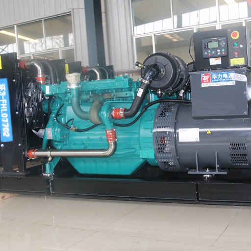
Record the application and operating boundary
Start with the owner’s operating objective. Is this standby generation for a facility, an isolated supply, or a plant with a proposed utility-parallel mode? The answer shapes the required connections and sequences.
CAT’s guide to specifying paralleled generation systems begins with design criteria and topology. Use that approach without treating its older code references as current project approvals.
Attach a one-line diagram with a document number and revision. Show the generators, bus sections, ties, utility sources and transfer equipment. Record generator identities, rating basis, voltage, frequency, site conditions and the loads served.
Mark future expansion separately from installed equipment. A proposed spare bay doesn’t establish that its future controls or studies are included.
Illustrative scenario: Two proposals both say “automatic paralleling.” One assumes an isolated generator bus; the other includes a utility breaker interface. The buyer marks the different boundaries on the one-line and asks both suppliers to price the same scope. This is a comparison example, not a reported customer result.
For an inquiry, send ZC Power your one-line, load list and required operating modes. Ask which items the proposed supply covers and which require others’ design or approval.
Assign drawings, studies and scope owners
Use the broader integrated standby system scope as context. Then assign the paralleling work. The set, switchgear and site work may come under separate contracts.
Name who supplies each item. The phrase “by others” leaves that question open.
| Scope question | Responsibility to name | Evidence to request |
|---|---|---|
| Which sets and controls are supplied? | Genset supplier. | Equipment schedule and controller identities. |
| Who integrates breaker and bus logic? | Switchgear integrator. | One-line, control drawings and sequence. |
| Who approves protection and earthing? | Project electrical designer. | Study and drawing references. |
| Who resolves utility conditions? | Named project coordinator with utility. | Applicable approval requirements. |
| Who tests and accepts the system? | Commissioning lead and owner signatory. | Test scope and closure responsibilities. |
Record the project location and system class. List the standard editions in the contract and the local approval needs. Ask the designer to resolve which apply; a manufacturer’s application guide cannot settle that decision for every site.
Keep exclusions visible, including site cabling, utility studies, existing equipment changes and acceptance attendance. Before comparing prices, check that each bid identifies the same boundary and the same unresolved inputs.
Write operating modes as observable sequences
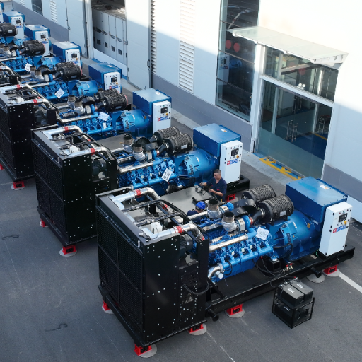
Separate the island bus from the utility connection
Generator-to-generator operation does not establish permission to connect generators in parallel with the utility. Mark each proposed mode as required, excluded or conditional. For a conditional mode, identify the approval needed before it can become part of the accepted design.
For each mode, start with the state of the plant. What triggers a change? Who permits it?
State the required action, the load response and the return state. Include the response when the expected action fails. The Eaton paralleling switchgear design guide, dated February 2025, illustrates common-bus and mains/generator arrangements.
Its examples help frame questions; the approved project sequence must define the supplied system.
| Mode to select | Preconditions and authority to identify | Load, exception and record questions |
|---|---|---|
| Island black start. | Dead-bus detection and first-close arbitration. | What load is admitted, and what records a failed start? |
| Additional set to live bus. | Synchronizing and close-permission owners. | When may the incoming set accept load; what happens on timeout? |
| Load-demand operation. | Capacity inputs and start/stop logic owner. | Which loads remain admitted if another set is unavailable? |
| Open-transition utility return. | Source qualification and transfer authority. | What interruption is planned; how is failed return recorded? |
| Closed or extended utility parallel. | Utility approval and selected protection basis. | What limits apply; what ends or blocks the mode? |
| Test, manual or maintenance. | Operator permissions and available sources. | Which automatic actions remain enabled; how is normal restored? |
Link each selected row to a drawing revision and its planned test record. Mark excluded modes clearly. A label on a screen should not change the agreed scope.
State test, manual, maintenance and return sequences
A dead bus has no supply. Dead-bus arbitration decides which source may connect first. A live bus already has power, so an incoming source needs synchronization.
An automatic synchronizer acts to match the sources. Sync-check tests whether they meet the approved close criteria. Ask where these functions reside and how they interact.
Don’t substitute a generic angle or frequency window for the selected equipment’s approved settings.
The transfer-switch transition guide provides adjacent terminology for the transfer layer. Keep the paralleling sequence tied to the actual one-line: an automatic transfer switch (ATS) and a generator breaker may have different roles and control owners.
Manual selection also needs a written sequence. Identify which interlocks remain active, which commands the operator can initiate and which remote commands are blocked. Document maintenance isolation and restoration conditions.
For test mode, say whether real facility loads, a load bank or simulated inputs are involved. The reviewer should be able to ask, “What state follows this event?” and find a named answer, including when normal supply returns during a test.
Document generator paralleling interfaces and ownership
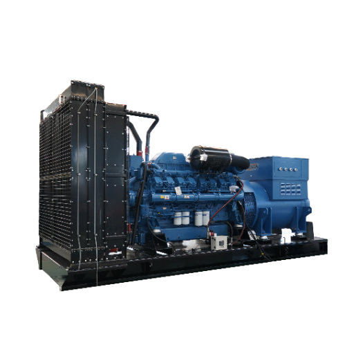
Separate governor, AVR and protection interfaces
An interface register is a list of links between devices. It shows what each link must do and who owns it. For each function, name both ends and the signal or protocol.
Link the drawing and test record. State what happens in normal use and on a fault. Who may issue commands, and who must make the link work?
Add range, scaling, units and update behavior where data values are involved. Mark open fields. A blank cell does not mean the function is excluded.
The governor and automatic voltage regulator (AVR) serve different control roles. Real power is measured in kW. Its sharing relates to engine and governor control.
Reactive power is measured in kVAr. Its sharing relates to excitation and voltage control. Cummins T-016, Issue 4, June 2014, explains these distinctions in its paralleling-control sections. Use it for engineering background.
It does not grant current approval or show how to wire a different platform.
Use the following rows to collect project-specific details:
| Function | Source and destination to identify | Definition and evidence to attach |
|---|---|---|
| Remote start and ready. | Plant/ATS to set controller and return. | Command meaning, ready conditions and functional check. |
| Speed and kW sharing. | Governor and load-share control. | Supported interface, allocation basis and response record. |
| Voltage and kVAr sharing. | AVR and reactive-share control. | Selected scheme, limits and verified response. |
| Current/voltage sensing. | CT/VT circuits to controls and protection. | Phase assignment, ratios and checked drawings. |
| Breaker control and status. | Controller, breaker and protection. | Position, trip, close permission and mismatch response. |
| Transfer coordination. | ATS and plant controller. | Inhibit, available-source and retransfer definitions. |
| Protection and earthing. | Study/drawing to supplied equipment. | Approved references, settings owner and verification scope. |
Current transformers (CTs) and voltage transformers (VTs) send measured values to the controls. The drawings must identify each device and its assigned phase. Leave pinouts, cable sizes, relay settings and neutral bonds to the designer and the chosen equipment documents.
Separate autonomous control from supervisory data
Extend the register to the load-share network, master controller, control power and building management or supervisory systems (BMS/SCADA). Name both ends of each path. For network data, include the data map, units and scale.
State who may write values. How does the system flag old data, and what happens if data is lost? For control power, ask what feeds each device and what shares that feed.
Record the alarms and tests.
Check monitoring and control separately, even if they share a device. A screen showing a breaker as open doesn’t prove the controller has the correct close permission. The limits of remote monitoring matter here: visible status is useful, but it cannot replace a functional interface check.
Illustrative scenario: A review screen shows a healthy source while the agreed load-inhibit feedback has no recorded check. The reviewer leaves that interface row open and asks who supplies the signal, which state blocks load admission and what test will demonstrate it. The scenario does not assume the hardware has failed.
The Eaton guide separates supervisory and load-sharing functions and warns that typical interconnections need project submittals. Apply that distinction to the supplied architecture. The word Ethernet does not say which commands take priority.
It does not define the supported functions or how the system recovers. If local and remote controls can both issue a command, ask which wins and how operators can see the active authority.
To clarify a proposal, discuss the open interface list with ZC Power. Request confirmation of the offered scope and exclusions; don’t assume every requested interface is available.
Define load management and failure-response responsibilities
Separate admitted load from online generating capacity
Load-demand start/stop changes which generators are online. Load add/shed changes which loads the plant admits. Define both.
Adding a source and adding a load are separate decisions. Ask for the load list, priority groups, permitted source states and the approved conditions for admitting or removing each group.
What capacity does the plant count if a set fails to start or synchronize? What changes if a running set disconnects? Write down the answers.
Total nameplate kW alone does not answer that question. Ask the designer to check the duty basis and each set’s limits. For unequal ratings, review the intended proportional loading basis rather than assuming every set should carry equal kW.
Check reactive load too. A kW display alone does not show whether each alternator stays within its reactive limits. Ask how the selected controls share kW and kVAr and which evidence will show acceptable behavior for the approved configuration. Keep the sums and settings in the project studies.
The discussion of N+1 capacity and failure paths is a useful companion. A spare set addresses a capacity question; shared controls, networks and power supplies require their own review. Ask which dependencies remain common before accepting a broad redundancy claim.
Specify degraded states and controlled recovery
Create a failure-response register alongside the operating-mode table. For each event, state what may keep running and what alarm must appear. Name the response owner.
Define when a reset is allowed, who permits recovery and what record is needed. Use the response in the approved design. A rule to trip every set if data is lost cannot fit every control function.
| Event to review | Question the approved design must answer |
|---|---|
| Set unavailable or failed start/synchronization. | Which loads remain permitted, and who requests another source? |
| Breaker command/status mismatch. | Which actions are blocked and where is the discrepancy reported? |
| Load-share path lost. | Which control functions remain available and under what limits? |
| Master controller or operator screen lost. | What remains autonomous and what operator access is retained? |
| Control-power supply lost. | Which devices lose function and what separate alarm path remains? |
| Utility returns or supervisory data becomes stale. | What permits return and prevents use of invalid information? |
Follow each event through recovery, not just the first alarm. If a network returns, does the plant resume automatically or wait for acknowledgement? If a set returns to service, what permits its re-entry and the restoration of shed loads? Assign the answers to the sequence owner and commissioning lead.
Continue the missing-feedback scenario from the interface review: restoring visible data does not close the original functional question. Request the agreed recovery check and its record. This keeps availability claims tied to demonstrated behavior without inventing an uptime percentage or promising interruption-free operation.
Tie acceptance evidence to the approved specification
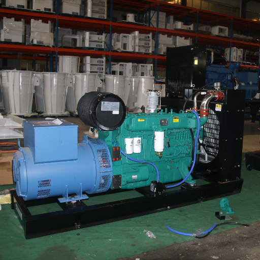
Separate factory, simulated and site-dependent checks
A generator paralleling specification becomes testable when each selected behavior has an agreed acceptance criterion and a traceable record. Define factory acceptance testing (FAT) and site acceptance testing (SAT) scope before release. Identify the equipment connected during each check, the inputs simulated and the installation conditions that remain outside it.
A load-bank report can document the loading performed, but does not by itself prove every transfer, protection or site-control interface. Cummins T-016 includes separate factory and startup/acceptance record categories. Use those categories to ask what the project actually tested, rather than carrying over an assumed test duration or an old standard edition.
Illustrative scenario: A factory sequence check uses a simulated ATS input. The buyer records that boundary and retains the real ATS-response check for site acceptance. The simulation is identified as such; neither the unconnected ATS nor the complete installed sequence is described as passed.
For a containerized package, the factory acceptance dossier helps organize package records. Keep enclosure checks separate from control tests. Link the records where their scope meets.
Agree the witness and sign-off roles before testing. Ask who supplies test equipment, who records observations and who can close a finding. If the contract calls for a witness, keep that record. A report saying “pass” needs a test criterion, a record of the setup tested and a named signer.
Record settings, findings, retests and handover
Build an acceptance ledger with requirement ID, mode/interface, approved document revision, criterion owner, method, actual or simulated inputs, observed result, record reference and closure authority. The following is an uncompleted example row, not evidence of a successful test:
| Ledger field | Example entry for planning |
|---|---|
| Requirement. | Incoming generator added to an energized island bus. |
| Controlling documents. | Approved source-add sequence and interface drawings; revisions to be entered. |
| Criterion owner. | Named project designer with integrator input. |
| Method. | Authorized functional test; list connected devices and simulated inputs. |
| Acceptance reference. | Approved permissions, load acceptance and abnormal-response criteria. |
| Result and record. | To be entered from the witnessed or recorded test. |
| Finding, retest and closure. | Record any deviation; named owner accepts relevant retest evidence. |
Each report should name the controller, firmware and settings used. Record the revision of the saved control setup. Retain approved backups with access and restore responsibilities.
If the setup changes after a test, ask what that change affects. The designer and integrator should name the checks that must be run again. A new file name does not prove that the revised sequence was tested.
At handover, request the as-built one-line and control drawings, final interface register, load-priority table, settings/configuration records and test reports. Keep open site items in a list. Name who must close each one and what record will prove it.
Record training and handover scope separately from equipment tests. The owner can then see what the factory checked, which deviations were accepted and what still needs a site test. Those are different decisions.
Frequently asked questions and project handoff
Does parallel-ready include utility paralleling?
No. The term alone does not define which sources may be connected. Generator-to-generator operation on an isolated bus and operation in parallel with the utility have different scope and approval questions. Require the selected mode, approved one-line, protection basis and utility conditions to be identified before accepting utility paralleling as included.
Ask the supplier to mark any excluded connection on the proposal drawing.
Is synchronization the same as load sharing?
No. Synchronization matches an incoming source to a live bus before it connects. Load sharing controls how the connected sets carry real and reactive load.
Name the synchronizing and close-permission functions in the specification. Then define the kW/kVAr sharing scheme, each set’s limits and the tests needed to accept it.
Keep both functions visible in the interface register and test scope.
Can different generator sizes or makes run together?
The actual sets and their controls need review first. Check the governors, AVRs, controllers, protection and proposed links. Brand names and ratings alone do not settle the question. Ask how the supplied sets will work together, what load limits apply and which tests cover the chosen modes and fault responses.
Do not turn a general compatibility statement into approval of an unidentified retrofit.
Does a communications protocol prove compatibility?
No. A protocol name does not tell you which data points work, who may issue commands or what happens if data stops. Ask for the exact interface details for both devices and the approved setup. Name the tests that will check commands, permissions, status and recovery against the agreed design.
A data-map review and a functional test answer different parts of that question.
Does a load bank report prove the whole paralleling system?
No. Read the scope to see which sets, loads and controls were tested. The result cannot prove how unconnected site links or untested modes will work.
Match each requirement to its own record. Mark simulated inputs clearly, and keep checks that need the installed plant in the site test plan.
An open site check needs an owner and closure evidence, not an assumed pass.
Prepare the review package
Before approval, collect the one-line, set/controller details, load priorities and selected modes. Add the interface register, named owners, approval basis and FAT/SAT scope. List the open questions. Suppliers can then answer the same brief, and the owner can see which decisions remain.
Use the same review habit in each scenario: compare scope, check the function behind a display and separate simulated inputs from real site tests. Keep each unanswered requirement visible until the responsible party supplies the agreed document or result.
Share your project requirements with ZC Power to discuss the proposed generator supply and confirm scope. Include the open acceptance questions with the load list and one-line so the inquiry starts with the decisions that matter for your project.


