Paralleling Dissimilar Generators for an Industrial Retrofit
Paralleling dissimilar generators can be feasible when their engines, alternators and controls work together in the required modes. A retrofit decision needs evidence for that combination. Review its load response and assign responsibility at each interface.
A quotation may describe a new set as parallel-ready while leaving the existing controller unidentified. That gap matters to an owner deciding which equipment to retain. This guide explains how to turn a broad compatibility statement into a document register that supports a scoped decision.
Start with the whole-project requirements in your generator paralleling specification. Then use the checks below to examine the existing plant and proposed additions together. The focus is industrial synchronous generator sets and the records needed for a retrofit review.
Key Takeaways
- Identify the assembled set, controller, governor and excitation equipment by model and revision.
- Review real-power, reactive-power and transient behavior separately.
- Assign an owner to every control interface and allowed operating combination.
- Record evidence gaps and closure actions before accepting a compatibility claim.
Have an existing plant to describe? Send its one-line diagram and equipment identities when you contact ZC Power to discuss the proposed supply scope.
Define the Existing Plant Before Paralleling Dissimilar Generators
Identify the old and proposed equipment
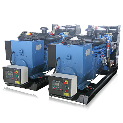
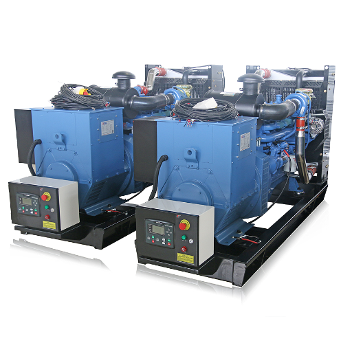
Begin with an identity schedule for every set that may operate on the common bus. Include the assembled-set serial number, engine, alternator, controller, governor and automatic voltage regulator, or AVR. Record hardware options, firmware versions and the document revision supporting each entry. A replacement controller fitted during maintenance can make an original panel drawing incomplete.
Keep rating information beside equipment identity. Request the applicable duty rating, voltage, frequency, phase arrangement and site conditions used for the proposed output. Ask the equipment supplier to identify relevant limitations. Comparing sets on different rating bases can distort the capacity available for the intended duty.
Establish the existing machine’s condition before pricing interface changes. Cummins recommends checking existing equipment under a dedicated load before modifying it for parallel operation. A baseline report should identify the tested machine and describe voltage and frequency behavior at the stated load. Unexplained instability needs an assigned investigation before the retrofit design relies on that machine. Cummins Power Topic 9015
Illustrative scenario A
An existing set and proposed addition have matching nameplate voltage and frequency. The proposal contains no controller revision or interface schedule. The buyer requests the missing identities, baseline report and current drawings, leaving the compatibility decision pending. This example describes a document review with no assumed test outcome.
Separate isolated-bus and utility boundaries
Mark the intended electrical arrangement on the one-line. Identify the common bus, generator breakers, bus ties, transfer equipment and any utility connection. State which modes the project needs, including isolated operation and any proposed utility-parallel mode. Give each mode a clear approval boundary.
A dead bus is de-energized, while a live bus already has voltage present. Record who controls starts, first closure onto a dead bus, synchronization onto a live bus and permission to admit load. Identify local manual controls as well as automatic commands. The reviewer needs to understand which device has authority when several controllers request an action.
Ask the owner to provide marked-up changes and maintenance records along with the original drawings. Label unverified drawings accordingly. Assign a person to reconcile discrepancies between documents and installed equipment, with a due date before design approval.
Can the project define the existing configuration well enough to evaluate a retrofit route?
Separate Engine, Alternator and Load-Response Compatibility
Compare assembled-set transients
Real power, measured in kW, relates to engine output and governing. Reactive power, measured in kVAr, depends on excitation and the electrical system. A mixed fleet needs both channels reviewed. Equal steady frequency leaves questions about how the machines respond when a large load arrives or disappears.
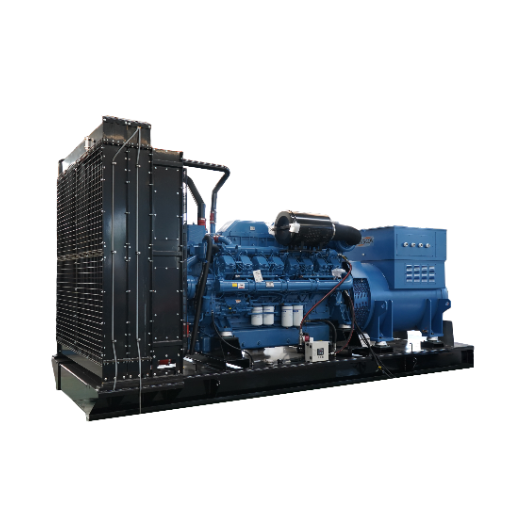
Request assembled-set load application and rejection data under identified conditions. Engine-only response information and alternator-only voltage-dip data describe parts of the system. The complete set combines the engine, governor, alternator and excitation response. Cummins discusses unequal transient behavior as a compatibility issue, including its potential effect on sharing and protective operation. Cummins Power Topic 9015
For the agreed combined-system cases, ask for simultaneous records of each set’s kW and kVAr together with bus voltage and frequency. Record the load condition before and after the event. The responsible designer and commissioning team should define the method, limits and assessment period before testing. This lets the reviewer distinguish a stable endpoint from an acceptable transition.
Use this evidence matrix to keep separate questions visible.
| Review layer | Record to request | Decision it supports |
|---|---|---|
| Existing-set condition | Identified baseline test and unresolved defect list | Whether the machine is a viable retrofit candidate |
| Load response | Assembled-set application and rejection data with initial conditions | Which proposed load events require further assessment |
| Real and reactive sharing | Simultaneous per-set kW and kVAr records | Whether both channels meet the agreed allocation criteria |
| Alternator and excitation | Alternator identity, winding data, AVR details and manufacturer review | Whether the proposed electrical combination is supported |
| Neutral arrangement | Current drawings and assigned engineering review | Whether the studied arrangement matches the intended plant |
Keep neutral and synchronization evidence visible
Alternator differences also need attention. Cummins discusses waveform differences and circulating neutral currents as possible sources of heating or interference with protection. Request the alternator and neutral arrangement data needed by the responsible engineer. Keep any resulting restrictions attached to the specific equipment combination.
Synchronization has its own equipment and breaker conditions. STAMFORD’s AGN022 discusses matching conditions and breaker closing delay, including the consequences of incorrect synchronization. Obtain the selected equipment’s guidance and actual breaker information for the project review. STAMFORD AGN022
Illustrative scenario B
A proposal includes a standalone resistive load-bank report and a broad mixed-fleet compatibility statement. The reviewer records what the test demonstrates, then leaves combined transient and reactive-sharing evidence open. The closure action identifies the additional agreed cases and their acceptance owner.
For the detailed allocation questions, use the separate generator load-sharing review. Keep this retrofit matrix focused on whether the actual old and new equipment can deliver the required behavior together.
Map the Retrofit Control Interfaces and Responsibility
Distinguish governing, excitation and supervisory control
Draw the control functions separately from the power circuit. Identify the path that regulates engine power, the path that regulates excitation and the devices that coordinate load sharing. Add the supervisory system that requests starts, stops or operating modes. Show where each command enters the equipment.
A monitoring connection may expose values without controlling either sharing channel. Who commands each function? Ask the integrator to identify the real-power and reactive-power command and feedback paths.
Record the device responsible for each function in every permitted mode. A supervisory power-management system and a local controller can have different roles in the same plant.
The DEIF AGC-4 Mk II designer’s handbook describes several analogue load-sharing types and associated hardware arrangements. Its sections on load sharing distinguish supported interface choices and signal details. Use the applicable manual revision to identify the proposed connection, scaling and equipment options. DEIF designer’s handbook
A proposal may retain the existing control system, add an interface, or replace selected controllers. Compare those routes against documented equipment support, required panel changes, test access and ownership of configuration. Request a list of functions covered by each route. The selected route still needs project-specific approval.
Document the actual signal and authority
Build one interface entry for each function and include these fields.
- Name the transmitting and receiving devices, models and revisions.
- Identify the hardware options and permitted operating mode.
- Define the signal, units and scaling.
- Reference isolation and grounding requirements in the selected equipment documents.
- Name the configuration owner and the function approver.
For load sharing, identify real and reactive channels explicitly. For breaker control, identify the source of close permission, breaker feedback and the documented behavior when feedback is missing. For first-start control, show which device arbitrates dead-bus access. Cross-reference the generator synchronization requirements for the pre-close evidence review.
For a proposed gateway, request written support for the named device versions and required control functions. Keep that claim conditional until its scope and verification are agreed.
Illustrative scenario C
An interface proposal lists a gateway and a familiar connector, but omits its function schedule. The reviewer asks for supported device versions, the kW and kVAr paths, signal definitions and configuration responsibility. That interface remains pending until the supplier documents the proposed implementation and the project accepts its verification scope.
Ask ZC Power which proposed supply interfaces and supporting documents are included when requesting a quotation. Identify third-party controller work, existing-panel changes and site testing as separate scope questions. A written response should show who supplies and accepts each item.
Keep a configuration record with approved parameter-file references and a revision history. Record who may change the interface after acceptance. If a controller or AVR later changes, the owner can then identify which compatibility conclusions need review and which records describe the current plant. This traceability also helps compare an offered factory configuration with the equipment eventually installed.
Review the Operating Envelope for the Mixed Fleet
Check first usable capacity and allowed combinations
List the combinations the plant must support. Include each set alone, required parallel groups, maintenance exclusions and the combinations remaining after a unit becomes unavailable. For every entry, identify the available rating basis, admitted loads and control mode. This schedule gives compatibility a defined operating envelope.
Illustrative arithmetic
Suppose a plant has nominal ratings of 400 kW and 800 kW. Their sum is 1,200 kW, while a proposed 500 kW first load block exceeds the smaller set’s nominal 400 kW rating. The review must identify which set can energize the bus first and which load may then be admitted.
This arithmetic is only an initial capacity check. Actual load acceptance also requires the relevant site rating, load characteristics and dynamic response assessment. Even a block below a nameplate rating needs that assessment. The sequence designer should document how the plant handles a smaller first-available machine and an unavailable larger machine.
Extend the schedule to load rejection and removal of an operating set. Record the load that remains, the permitted combination and the associated control response. The detailed generator load-management guide covers add, shed, start and stop sequencing. Here, identify the retrofit evidence needed to support those sequences on the mixed fleet.
Assign protection and earthing decisions
Keep protection studies, neutral arrangements and earthing decisions assigned to the responsible design professionals. Their input list should match the actual alternators, breakers and permitted system configurations. Ask who approves changes when the retrofit adds a machine or changes the available fault contribution.
Document the scope of utility requirements where a utility connection is involved. Request the relevant permissions and project requirements from the party responsible for that interface. The operating schedule should make excluded modes visible to both the designer and the future operator.
Include loss of the proposed sharing or supervisory interface as a review case. Ask the supplier to state the resulting mode, alarm and control authority, then identify how the project will verify that response. Keep detailed failure-recovery procedures in their own approved documents. The compatibility decision needs a clear reference to them and a named closure owner.
Turn Compatibility Claims Into an Acceptance Register
Give each claim a disposition
Use a register to connect the proposal’s claims with specific equipment and evidence. The format below is a practical review aid. Adapt its fields to the contract and the responsible engineering team’s process.
| Register field | What to enter |
|---|---|
| Claim and scope | The proposed function, permitted mode and equipment combination |
| Equipment identity | Set serials, controller and AVR models, hardware options and revisions |
| Supporting document | Manufacturer guidance, drawing or approved configuration reference |
| Evidence condition | Tested or simulated arrangement, initial load and event |
| Observed record | Report, event log or trace covering the stated condition |
| Acceptance responsibility | Criterion reference and the person authorized to assess it |
| Disposition and action | Supported, conditional, excluded or pending, with owner and due date |
Keep the choice of retrofit route distinct from the evidence disposition.
Retaining equipment requires support for its intended role. Adapting an interface requires a documented supported implementation and verification. Replacing a controller requires review of the functions and protection interfaces affected. Excluding a mode requires the operating documents to reflect that limit.
A useful row contains a narrow claim. For example, identify the real-power sharing function between the named controllers in the agreed isolated-bus mode. Add a separate row for reactive sharing if its evidence differs. This prevents a supported communication channel from silently closing an unrelated electrical-performance question.
Separate factory, simulated and installed evidence
Record the equipment present in each test.
A factory report may cover the new set with representative control equipment. A simulation may cover logic under stated assumptions. An installed test can address the actual plant arrangement within its recorded conditions. Each record needs a scope that the reviewer can compare with the claim.
When the original machine is absent from a factory test, identify how the project will close that interface at site. If simulation substitutes for unavailable equipment, list the substituted signals and remaining checks. Agree which records are required before shipment and which belong to site acceptance. This makes outstanding work visible during procurement.
Request a report identifier, tested configuration, instrument or data-source references, event description, observations and reviewer disposition. For traces, ask for labelled units and a common time reference so the event can be compared across machines. Attach deviations to the affected claim.
For example, give a pending reactive-sharing row an owner and an agreed test-record reference. Record the criterion it must satisfy and who will assess the result. A revised parameter file or controller version should trigger review of the relevant rows before earlier results are reused.
The illustrative scenarios can therefore close in different ways. The identity gap may remain pending, the standalone test may support only its recorded condition, and the gateway proposal may require a documented adaptation. Record these outcomes honestly, with the next action assigned. The register can guide a purchasing decision even while some combinations remain excluded.
For paralleling dissimilar generators, prepare the one-line, equipment schedule, required load cases and open register before comparing quotations. Send your project information to ZC Power and ask for confirmation of the offered supply scope, interface responsibilities and exclusions.
Paralleling Dissimilar Generators FAQ
Can different generator brands run in parallel?
Different brands may form a supported system when the actual engines, alternators, controls and interfaces meet the required operating conditions. Collect model-specific records and an approved scope for the combination. Brand names alone leave important questions about load response, reactive sharing, first-start control and acceptance responsibility unresolved.
Can generators with different kW ratings share a bus?
Different ratings require review of the allocation basis, transient response and allowed operating combinations. Check the first available set against the first admitted load and examine the loss of a larger machine. The combined nameplate total provides only one input to the capacity and sequence assessment.
Does every retrofit require replacement controllers?
The decision depends on the installed equipment, available interfaces and required functions. A supported interface may allow selected controls to remain, while other combinations may need replacement or an excluded mode. Request a function-by-function proposal and identify the documents and tests supporting whichever route the supplier recommends.
Does a standalone load-bank test prove mixed-fleet compatibility?
A standalone test supports conclusions within its recorded conditions and helps establish the existing set’s baseline. A mixed-fleet review also needs evidence for the agreed interfaces, reactive behavior, combined transients and operating combinations. Use the register to identify which claims the report supports and which require additional verification.
What if the old controller documents are missing?
Record the missing documents and assign an owner to identify the installed hardware and obtain applicable guidance. Keep the affected compatibility decision pending while that work proceeds. If the required evidence cannot be obtained, ask the responsible designer to evaluate a documented alternative, replacement or exclusion for that function.