Data Center Generator Sizing: Load, Redundancy, and Tier Requirements (2026)
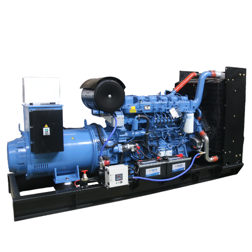
Data center generator sizing starts from the real IT load, multiplies it by the facility PUE to capture cooling demand, accounts for chiller motor starting surges, adds 20 to 30 percent headroom, and then converts to kVA at 0.8 power factor. For a Tier III facility, that total is then split across an N+1 configuration; for Tier IV, it is duplicated in a full 2N architecture.
The stakes have never been higher. According to Gartner’s 2026 forecast, global data center electricity consumption will jump 26 percent this year to 565 TWh, with AI-optimized servers accounting for nearly a third of that demand. Power availability, not servers, is now the binding constraint on data center growth. Grid interconnection queues stretch up to four years in some markets, which means the genset plant is no longer just emergency equipment. For many operators, it is the only guaranteed power source the facility will ever have.
In 25 years of manufacturing gensets at our facility in Jining, Shandong, we have supplied standby and prime power plants for data centers, hospitals, and colocation facilities across more than 50 countries. This guide gives you the complete sizing method our engineers use: the six-step load calculation, the redundancy architectures behind the Uptime tiers, and two fully worked examples, including one for a 100 kW-per-rack AI hall.
Key Takeaways
- Size from measured IT load, not nameplate ratings. Multiply by PUE (typically 1.2 to 1.6) to capture cooling, then add 20 to 30 percent headroom and convert to kVA at 0.8 power factor.
- Chiller and CRAH motors can demand 2 to 6 times running kVA at startup. Check step-load acceptance, not just steady-state capacity.
- Tier III requires N+1 generator redundancy with 12 hours minimum fuel autonomy. Tier IV requires 2N or 2N+1 with up to 96 hours on site.
- Specify the ISO 8528-13 Data Center Power (DCP) rating, not a standby (ESP) rating. Data centers routinely exceed the runtime limits of ESP-rated machines.
- AI rack densities of 80 to 130 kW change the arithmetic completely: a 200-rack AI hall needs roughly ten times the generator plant of a legacy hall with the same rack count.
Why Data Center Generator Sizing Is Different
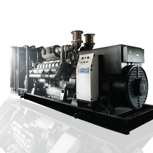
Sizing a genset for a factory or commercial building is mostly about peak demand. Data centers add three complications that change the entire exercise.
The UPS Only Buys You Seconds
The UPS bridges the gap between utility failure and genset synchronization, typically 10 to 30 seconds. Everything after that belongs to the generator plant. If the gensets cannot carry the full facility load, the UPS is an expensive delay, not a solution.
Cooling Rivals IT as a Load
Servers are only about half the story. Chillers, CRAH units, and pumps consume 35 to 55 percent of IT load in a typical facility. The global average PUE sits around 1.55, and Gartner estimates cooling infrastructure alone will consume 195 TWh in 2026. Any sizing method that starts and ends with server wattage will undersize the plant by a third or more.
Tier Requirements Turn Sizing Into Architecture
A commercial building needs a generator. A Tier III data center needs a generator system: multiple units, paralleling switchgear, staged restart logic, and enough fuel for 12 hours minimum. The N+1 vs 2N decision happens before the capacity decision, because it determines how many units share the load.
The 6-Step Data Center Generator Sizing Method
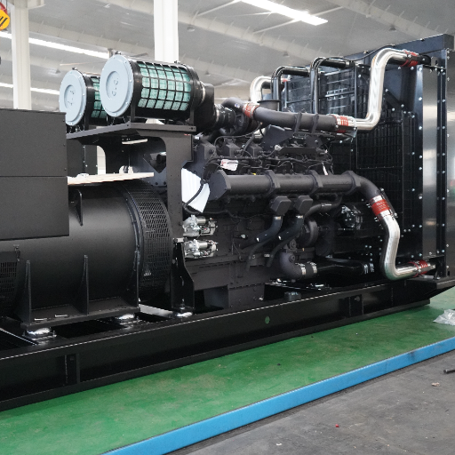
This is the procedure our engineering department applies to every data center project. It builds on our general generator sizing methodology, adapted for the loads and uptime requirements of a data hall.
1. Measure the Real IT Critical Load
Use actual UPS output in kW, not server nameplate ratings. Nameplates assume worst-case configurations that almost never occur; measured draw at peak is typically 60 to 80 percent of nameplate. If the facility is not yet built, work from the IT design capacity with a realistic diversity factor.Because the gap between nameplate and measured draw is where most oversizing errors begin, our dedicated guide to generator load calculation shows how to turn measured feeder readings into a defensible demand figure step by step.
2. Add the Mechanical Load
Chillers, CRAH fans, condenser pumps, and humidification all ride on the generator during an outage. In an air-cooled facility this adds 35 to 55 percent on top of IT load. Liquid-cooled AI halls run lower PUE but add CDU pumps and, often, larger heat rejection systems.
3. Apply the PUE Multiplier
The shortcut for steps 1 and 2 combined: total facility load equals IT load multiplied by PUE. Use the design PUE, not the marketing PUE. A facility designed at 1.4 but operating at 1.55 in summer ambient conditions will leave the genset plant short exactly when the grid is most stressed.
4. Account for Motor Starting Surges
When utility power returns after a blip, or when the plant restarts after a test, every chiller tries to start. A 400 kW chiller started direct-on-line can demand 2 to 6 times its running kVA for several seconds. The genset plant must absorb this step load without a voltage dip deep enough to trip UPS systems or drop contactors. The full method, including locked rotor amps and the voltage dip formula, is covered in our guide to motor starting generator sizing.
5. Add Headroom and Derating
Add 20 to 30 percent for growth, alternator aging, and step-load margin. Then apply environmental derating: gensets lose roughly 10 percent of capacity per 1,000 meters of altitude, and high ambient temperatures cost several percent more. A site at 1,500 meters and 40°C can lose a fifth of its nameplate capacity before the first server is racked.
6. Convert to kVA and Select the Rating
Divide kW by 0.8 power factor to get kVA. Then, critically, select the correct ISO 8528 rating. For data center duty, that is the Data Center Power (DCP) rating, not a standby rating. More on this below. For the conversion math itself, our kW to kVA conversion reference covers both directions.Since large data halls almost always distribute power as three-phase at the plant level, our guide to three phase generator sizing explains how to apply the √3 formula across wye and delta configurations and keep the phases balanced as you lock in the final rating.
Redundancy: N, N+1, 2N, and 2N+1 Explained
Redundancy notation describes how much spare generator capacity exists relative to what the facility actually needs:
| Configuration | Meaning | Example for a 6 MW Load | Uptime Tier |
|---|---|---|---|
| N | Exactly enough, no spare | 3 × 2 MW | Tier I |
| N+1 | One spare unit | 3 × 3 MW (2 running + 1 spare) | Tier II–III |
| 2N | Two complete independent systems | 2 plants × 6 MW each | Tier IV |
| 2N+1 | Two systems plus one spare | 7 × 3 MW across two plants | Tier IV (enhanced) |
The distinction that matters in practice: N+1 allows concurrent maintainability, meaning any single genset can be serviced while the rest carry the full load. 2N provides fault tolerance, meaning an entire power path, including its switchgear and distribution, can fail without interrupting the IT load. Per the Uptime Institute topology standard, that difference is what separates Tier III from Tier IV.
When Daniel, an EPC project manager we worked with on a colocation build in Johor, Malaysia, priced his Tier III design, he initially specified four identical 2,000 kVA units in N+1 for a 4.5 MW critical load. The review caught a problem: at night, the load dropped below 40 percent, and all three running units would have operated in the wet-stacking zone for months. The final design used six 1,250 kVA units instead. Fewer units run at light load, each stays in its efficient 70 to 80 percent band, and the same N+1 requirement is met. Redundancy architecture is about unit count and unit size, not just total capacity.
Uptime Tier Requirements for Generators
The tiers translate directly into generator plant requirements:
| Tier | Generator Redundancy | Fuel Autonomy | Runtime Expectation |
|---|---|---|---|
| Tier I | N (single path) | 8–12 hours typical | Short outages only |
| Tier II | N+1 components | 12 hours | Limited redundancy |
| Tier III | N+1, concurrently maintainable | 12 hours minimum | Multi-day events expected |
| Tier IV | 2N or 2N+1, fault tolerant | 96 hours | Extended regional outages |
Two details are worth underlining. First, Tier III and IV assume the gensets may run for days, not hours, which is why the DCP rating matters. Second, fuel autonomy is about delivered fuel, not just tank size. A 96-hour tank is useless if the refueling contract cannot survive a regional flood. For the standby-duty context and emergency-system framing, see our guide to standby generator sizing.
Worked Examples
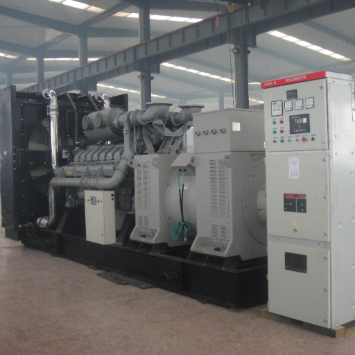
Legacy Enterprise Facility: 2 MW IT Load, Tier III
A financial services data hall, 2 MW measured IT load, design PUE 1.5, sea-level site, Tier III target.
- Facility load: 2 MW × 1.5 = 3.0 MW
- Headroom at 25 percent: 3.75 MW
- Convert to kVA: 3,750 / 0.8 = 4,688 kVA
- Chiller check: two 400 kW chillers, soft-started at 2.5× inrush, staged 15 seconds apart; step load fits within the plant’s transient response
- Selection: 4 × 1,600 kVA in N+1 (three running, one spare), 4,800 kVA installed, 12-hour base tanks plus day tanks
AI Data Hall: 200 Racks at 100 kW per Rack, Tier III
Same rack count as the legacy example would imply, but at AI densities: 200 racks × 100 kW = 20 MW IT load. Direct-to-chip liquid cooling brings design PUE down to 1.25.
- Facility load: 20 MW × 1.25 = 25 MW
- Headroom at 20 percent: 30 MW
- Convert to kVA: 30,000 / 0.8 = 37,500 kVA
- Selection: 15 × 2,500 kW containerized units, 14 running plus one spare per block, staged paralleling, medium-voltage distribution
- Fuel: 12 hours at full load means roughly 90,000 liters on site; the delivery contract matters as much as the tank
The contrast is the lesson. The AI hall needs roughly eight times the installed generator capacity of the legacy hall, a different voltage class, and a containerized multi-unit architecture rather than four units in a plant room. At this scale, the questions shift to paralleling, block redundancy, and lead times. Our guide to heavy duty diesel generator sizing covers the 500 kW and above territory in more depth.
Specifying the Right Genset: Rating, Paralleling, Fuel
Specify DCP, Not ESP
Most generator datasheets lead with the standby (ESP) rating. For data centers, that is the wrong number. ESP assumes a limited number of running hours per year at variable load, with the utility grid as the normal supply. A data center genset may run 48 to 96 continuous hours during a regional event, and grid-constrained facilities increasingly run on gensets during peak tariff windows as well.
The correct specification is the Data Center Power rating defined in ISO 8528-13, which is designed exactly for this duty: continuous or near-continuous operation at the full data center load profile. When we quote data center projects, the DCP rating is the headline figure, and every unit is verified against it with full load-bank testing in our national standard testing center before shipment.
Parallel Smaller Units or Install One Large One?
Above roughly 2 MW, multiple paralleled units almost always win over a single large machine. Paralleling gives you inherent N+1 granularity, lets running units stay in their efficient load band at night, and removes the single point of failure. The trade-off is paralleling switchgear cost and controls complexity. A modern synchronization panel with staged restart logic handles this, and it is standard equipment on the multi-unit containerized plants we build for data center and industrial clients.
Fuel Autonomy Is a Logistics Problem
Twelve hours minimum for Tier III, 96 hours for Tier IV. Size the base tank for at least the first 24 to 48 hours so the facility survives the initial chaos of a regional event, then secure redundant refueling contracts with guaranteed response times. Document fuel polishing and testing schedules; diesel stored for years without treatment is the most common reason a correctly sized plant fails to start.
Common Data Center Generator Sizing Mistakes
- Sizing from IT load alone. Ignoring cooling understates the plant by 30 percent or more. Always multiply by the real PUE.
- Forgetting chiller inrush. Steady-state capacity is not step-load capacity. Check the largest motor start against the plant’s transient response.
- Specifying an ESP rating for data center duty. The machine may physically fit the load and still be the wrong rating for the runtime the tier assumes.
- No growth headroom. Data halls densify. A plant sized to today’s 15 kW racks cannot absorb tomorrow’s 40 kW refresh.
- Deciding voltage too late. The low-voltage versus medium-voltage choice (415 V versus 10 kV class) changes cabling, switchgear, and genset configuration. Make it before the sizing calc, not after.
- Treating fuel as an afterthought. Autonomy targets are meaningless without contracts, access routes, and stored-fuel maintenance.
Frequently Asked Questions
What size generator does a data center need?
A data center generator plant typically needs 1.25 to 1.5 times the IT load to cover cooling, multiplied again by 1.2 to 1.3 for headroom and motor starting, then converted to kVA at 0.8 power factor. A 2 MW IT load at PUE 1.5 usually lands at 4,500 to 5,000 kVA of installed capacity.
How do you size a backup generator for a data center?
Measure the real IT load in kW, multiply by PUE to capture cooling, add 20 to 30 percent headroom, check chiller starting surges against step-load capacity, convert to kVA at 0.8 power factor, and finally apply the redundancy factor required by your tier: N+1 for Tier III, 2N for Tier IV.
How many generators does a data center need?
That depends on the tier, not just the load. Tier III requires N+1, meaning one spare unit beyond what the load demands; a 6 MW load might use three 3 MW units. Tier IV requires 2N, two complete independent plants. Multiple mid-size units are generally preferred over one large unit for redundancy granularity and efficient part-load operation.
What is the difference between Tier III and Tier IV generator requirements?
Tier III requires N+1 redundancy and concurrent maintainability, so any single genset can be serviced without dropping the load, plus 12 hours minimum fuel autonomy. Tier IV requires 2N or 2N+1 fault tolerance, meaning an entire power path can fail without affecting IT load, plus up to 96 hours of on-site fuel.
How long can a data center run on generator power?
Mechanically, a DCP-rated diesel genset can run continuously for as long as it has fuel. The practical limits are fuel autonomy (12 hours minimum for Tier III, 96 hours for Tier IV) and the refueling logistics that sustain extended operation during a regional outage.
What is a DCP rating and why does it matter?
DCP, or Data Center Power, is the ISO 8528-13 genset rating designed for data center duty: sustained operation at the full facility load profile for extended outages. It matters because the more common standby (ESP) rating assumes limited annual runtime, which a Tier III or IV facility will routinely exceed.
Should a data center use diesel or natural gas generators?
Diesel remains the default for Tier III and IV facilities because of its step-load response, energy density, and on-site fuel autonomy. Natural gas eliminates fuel storage but depends on a utility supply that can fail in the same regional event as the electric grid. Hybrid approaches exist, but diesel carries the critical load in most certified facilities.
Why can’t you size a data center generator from IT load alone?
Because servers are only about half the load. Cooling, pumps, and supporting infrastructure add 35 to 55 percent on top of IT load, and motor starting surges add transient demand several times larger still. Sizing from IT load alone undersizes the plant by a third or more.
Conclusion
Data center generator sizing comes down to six disciplines: measure the real IT load, multiply by the honest PUE, respect motor starting surges, add headroom for growth and derating, convert to kVA correctly, and specify the DCP rating your tier actually assumes. Then let the redundancy architecture, N+1 for Tier III or 2N for Tier IV, decide how many units share that capacity.
The expensive mistakes are all shortcuts: sizing from server nameplates, ignoring the chillers, or accepting an ESP datasheet for a facility that will run for days. Get your data center generator sizing right and the result is a plant that carries the hall through a four-day regional outage, runs each unit in its efficient load band, and scales with the next rack refresh.
At Shandong ZC Power CO., LTD., our team of 80+ engineers sizes and builds data center power plants across our 8 kVA to 4,000 kVA range, from single N+1 installations to containerized multi-unit plants with paralleling switchgear. Every unit is verified with full load-bank testing in our national standard testing center before shipment.
Send us your IT load profile, PUE target, and tier requirement, and our engineers will return a verified sizing calculation, redundancy architecture recommendation, and factory-direct quote built for your exact facility.