Stationary Generators for Data Centers: Redundancy, Sizing, and Fuel Strategy [2026]
Data centers use permanent diesel and natural gas generators which power all building operations within 10 seconds after electrical service stops. These systems provide essential power distribution for Tier III and Tier IV data centers because they deliver uninterrupted power necessary to meet all service level agreements.
Worldwide diesel generator capacity for data centers increased from 20 gigawatts in 2018 to 55 gigawatts in 2024. Northern Virginia now contains more than 10500 licensed permanent diesel generators which produce 27 gigawatts of electricity, enough to serve about 20 million American households. The substantial investment in permanent backup systems has failed to resolve power problems, which still account for 45 to 54 percent of serious data center outages because generator and integration system failures remain a major problem.
You already know that a single hour of unplanned downtime can cost a hyperscale facility hundreds of thousands of dollars. The actual cause of the problem occurs when people choose the wrong generator size and fail to integrate the UPS system and make permanent installation errors. We describe the complete process of specifying and sizing and deploying stationary generator systems for Tier III and Tier IV data centers through our guide which includes N+1 redundancy calculations and permanent fuel management and sound-proof installation methods.
Key Takeaways
- Stationary generators must assume critical load within 10 seconds per NFPA 110 Type 10, making permanent installation and automatic starting non-negotiable for data centers.
- Tier III requires N+1 redundancy with ISO 8528-1 Continuous (COP) or Prime (PRP) ratings; Tier IV demands 2N or 2(N+1) with fully independent power plants.
- Correct sizing requires applying PUE to IT load, adding UPS battery recharge surge, and including 20-25% growth margin before redundancy math.
- Stationary generators for data centers must be sized for the full facility load including PUE, UPS recharge, and growth margin before redundancy math is applied.
- Diesel commands 74-81% of data center backup power share, but natural gas and HVO are gaining ground for sustainability-targeted facilities.
- Permanent installation demands engineered concrete pads, remote cooling, sound attenuation below 75 dB, and 72+ hours of on-site fuel storage.
If you are new to permanently installed backup power, start with our complete guide to stationary generators for a foundation on types, fuels, and applications.
Why Data Centers Rely on Stationary Generators
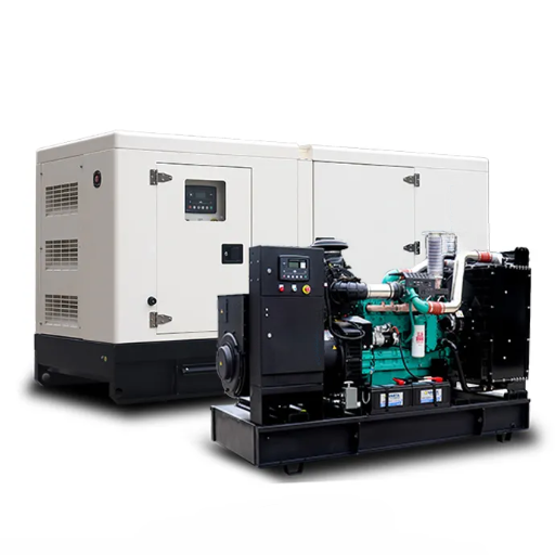
A stationary generator is a permanent power generator system that stays fixed at its installation site. The system supports a concrete base which contains permanent fuel lines and exhaust systems and connects to the building’s electrical network through physical wiring.
The data center power chain functions as an uninterrupted hierarchical structure. Utility power feeds the automatic transfer switch (ATS), which routes electricity through the uninterruptible power supply (UPS) to the power distribution units (PDUs) and finally to the IT load. The UPS batteries provide power during utility outages for 10 to 40 seconds until the stationary generators start running and take over complete facility operations through the ATS.
The required time of 10 seconds represents a mandatory obligation. NFPA 110 Type 10, Level 1 Emergency Power Supply System (EPSS) requires that critical load be assumed within 10 seconds of grid failure. From a cold start, this process requires block heaters and pre-lube oil pumps and redundant starters and control logic which needs permanent installation and ongoing system checks. The standard requires portable units to show dependable performance.
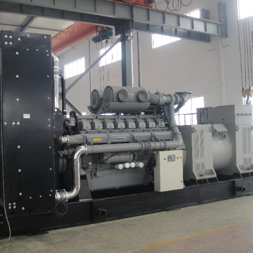
Diesel stationary generators currently dominate the market, commanding 74% to 81% of data center backup power deployments. The 350-800 kW capacity band represents the largest segment, driven by mid-tier colocation and enterprise facilities. The demand for AI infrastructure has resulted in increased needs from the market. A single NVIDIA GB200 NVL72 rack draws 120 kW, and next-generation clusters approach 1 MW per rack. The current generator specifications from the past fail to meet the necessary requirements for modern equipment.
If you are looking to select a stationary generator suitable for your specific application, we recommend first reading our Stationary Generator Selection Guide to receive more detailed recommendations.
Uptime Institute Tier Requirements for Data Center Generator Plants
The Uptime Institute Tier classification system defines the reliability architecture that every data center stationary generator plant must support. Your Tier target determines not just how many generators you need, but how they must be wired, controlled, and tested.
Tier I and Tier II — Basic and Redundant Capacity
Tier I facilities operate with a single power path and no redundancy (N). Annual downtime can reach 28.8 hours. Tier II adds partial redundancy at the component level (N+1 partial), improving uptime to 99.741%, or roughly 22 hours of annual downtime. For these tiers, standby power rated generators (ESP) are often acceptable because runtime expectations are limited.
Tier III — Concurrently Maintainable (N+1)
The engineering work for stationary generators reaches its most advanced point at Tier III. The systems that deliver power must have every part designed for maintenance accessibility which does not disrupt operational IT systems. The stationary generator plant must support 100% of the facility load with any single generator unit offline.
The facility needs 3,000 kW of backup capacity which prevents you from using three 1,000 kW units as N+1. The two remaining units will operate at full capacity because the first unit failed. True N+1 redundancy data center design requires that N be the minimum capacity to carry the load, and the +1 be an identical unit beyond that minimum. The N+1 model for a 3,000 kW load requires three 1,500 kW generators which operate at 67% capacity while one generator stays on standby.
The Tier III standards require ISO 8528-1 Continuous Power (COP) and Prime Power (PRP) ratings for certification. The Standby Power (ESP) system fails to meet requirements because its ESP ratings depend on restricted annual operation and cannot assure reliable performance during constant or repeated use.
Tier IV — Fault Tolerant (2N or 2(N+1))
Tier IV demands fault tolerance with no single point of failure. This requires two completely independent electrical plants, each capable of carrying 100% of the facility load. A Tier IV stationary generator configuration might consist of two separate N+1 plants, each physically and electrically isolated, with separate fuel systems, switchgear, and distribution paths.
| Tier | Redundancy | Uptime | Annual Downtime | Generator Rating Required |
|---|---|---|---|---|
| Tier I | N | 99.671% | ~28.8 hours | Standby (ESP) acceptable |
| Tier II | N+1 partial | 99.741% | ~22 hours | Standby (ESP) acceptable |
| Tier III | N+1 full | 99.982% | ~1.6 hours | Continuous (COP) or Prime (PRP) |
| Tier IV | 2N / 2(N+1) | 99.995% | ~26.3 minutes | Continuous (COP) mandatory |
Data Center Generator Redundancy: N+1 and 2N Stationary Plant Design
Redundancy math is where most data center power designs fail. The concept is simple, but the execution is riddled with traps that have caused documented outages at major facilities worldwide.
Defining “N”
“N” equals the minimum generator capacity required to support the total facility load under rated conditions. Not the IT load. Not the nameplate capacity. The actual calculated facility load after applying PUE, UPS overhead, battery recharge, environmental derating, and growth margin.
N+1 Redundancy
N+1 means one spare unit beyond the minimum. The plant maintains full operation capacity when any generator breaks down. Load sharing typically runs each unit at 67% or less, which optimizes fuel efficiency and extends engine life.
Three 2,000 kW stationary generators supply power for a 4,000 kW facility load. The two units operate at 50% load while each unit produces 2,000 kW. The two remaining units operate at 67% capacity after one unit fails. This situation maintains both efficiency and manageability.
2N Redundancy
2N means two completely independent, mirrored power systems. Each system must carry 100% of the facility load independently. A 4,000 kW Tier IV facility might use System A with three 2,000 kW gensets and System B with three 2,000 kW gensets. Either system can carry the full 4,000 kW load. The systems must be physically separated so that a fire, flood, or electrical fault in one cannot propagate to the other.
Common N+1 Mistakes
The most expensive error is sizing N based on IT load alone. A Denver colocation facility made this exact mistake. Their engineering team calculated backup power using server nameplate ratings and ignored PUE. The computer room air conditioning (CRAC) units attempted to restart their operations when utility power failed. The stationary generator experienced a 22% voltage drop which caused it to shut down, resulting in a complete facility shutdown. The correction process needed a generator plant which was 40% bigger than existing equipment and required $85,000 worth of power system improvements.
Another common mistake is using one oversized generator instead of paralleled units. A single 4,000 kW block with a standby spare is not N+1. The spare must begin operation and establish synchronization while taking on power within the first seconds after the active unit breaks down. Paralleled stationary units distribute risk and enable concurrent maintainability.
How to Size Stationary Generators for Data Centers
Accurate sizing is an engineering discipline, not a spreadsheet exercise. The following methodology applies to permanently installed stationary gensets for mission-critical facilities.
Step 1: Calculate Critical IT Load
Inventory the actual power consumption of all critical IT equipment. For AI and GPU training clusters, use a diversity factor of 1.0 because these workloads draw near-nameplate power continuously during training runs. For legacy enterprise environments, a diversity factor of 0.60 to 0.75 is appropriate. Always use manufacturer thermal design power (TDP) watt ratings for modern equipment, not legacy VA nameplates.
Step 2: Apply PUE Multiplier
Total facility load is not just IT equipment. Multiply the IT load by your facility’s design Power Usage Effectiveness (PUE) to capture cooling, power distribution, and mechanical overheads.
- Efficient facilities: PUE ~1.2
- Average facilities: PUE ~1.5
Formula: Total Facility Load = IT Load × PUE
Step 3: Add UPS Overhead and Battery Recharge
Modern modular UPS systems operate at approximately 96% efficiency. The generator must also support peak battery recharge after an extended outage, which can reach 20% of the UPS rating for one to four hours post-recovery.
Formula: UPS Input Power = IT Load ÷ 0.96
Add: Peak Battery Recharge = UPS Rating × 0.20
Step 4: Apply Growth and Safety Margin
Add 20% to 25% for future expansion and environmental derating.
- Altitude derating: -3.5% per 1,000 feet above sea level
- Temperature derating: -1% per 10°F above 77°F
Step 5: Apply Redundancy Configuration
- Tier III: Size N for the buffered load using a prime power or continuous power rating, then add one identical unit (+1)
- Tier IV: Size two independent plants, each capable of full buffered load (2N)
Worked Example:
- IT load: 2,000 kW (AI training cluster)
- PUE 1.35 → Total facility load: 2,700 kW
- UPS input + recharge → 3,100 kW
- 25% growth margin → 3,875 kW
- Altitude derating at 3,000 ft (10.5%) → 4,280 kW minimum
- Tier III N+1 → three 1,600 kW stationary generators in parallel
- Tier IV 2N → two independent plants of three 1,600 kW generators each
The UPS Topology Multiplier
This is the most consequential and most overlooked variable. A legacy double-conversion UPS with high harmonic distortion requires a generator multiplier of 2.5× to 3.0× the UPS output rating. A modern active power factor correction (PFC) UPS requires only 1.25× to 1.3×. For a 500 kW UPS output, the difference is a 1,500 kW generator versus a 650 kW generator. That gap represents 500,000to500,000to800,000 in capital cost. Always confirm UPS topology before finalizing stationary generator specifications.
UPS, ATS, and Paralleling Integration
A properly sized stationary generator is worthless if it cannot integrate seamlessly with the facility’s UPS and transfer switch architecture.
The UPS Bridge
UPS batteries cover the 10- to 40-second gap between utility failure and generator stabilization. The stationary generator must be sized to handle the UPS battery recharge surge that occurs after extended outages. During normal operation, battery recharge draws less than 2% of UPS rating. After a multi-hour outage, peak recharge can spike to 20% of UPS rating for several hours.
Automatic Transfer Switch (ATS)
The automatic transfer switch (ATS) detects utility loss and transfers the facility load to the stationary generator plant. For Tier III/IV facilities, bypass isolation switches are essential, allowing maintenance and testing without interrupting power to the critical load. Closed-transition ATS enables zero-blackout testing by synchronizing the generator with the utility before transfer.
Paralleling Switchgear for Stationary Plants
N+1 and 2N configurations require paralleling switchgear to synchronize multiple stationary generators. Master-master distributed logic eliminates single points of failure. Each generator controller communicates with its peers to achieve isochronous load sharing, distributing load evenly across all running units. This architecture also enables seamless addition or removal of units for maintenance without load interruption.
For a deeper technical look at transfer switch requirements, see our generator transfer switch guide. For UPS integration specifics, review our UPS backup power overview.
Fuel Strategy for Stationary Data Center Generators
Fuel selection for permanently installed data center generators involves trade-offs between startup speed, emissions compliance, storage requirements, and total cost of ownership.
Diesel: The Dominant Standard
The diesel generator for data center applications remains the industry standard, holding 74% to 81% of market share because it achieves the sub-10-second start required by NFPA 110 Type 10. They deliver the highest motor-starting torque, critical for overcoming the inrush current of CRAC units and chilled water pumps. On-site fuel storage is mandatory. Tier III facilities typically maintain 72+ hours of diesel storage. NFPA 110 requires a 133% buffer above calculated consumption.
Fuel polishing is essential for long-term stationary storage. Diesel degrades over time, developing water contamination and microbial growth that clogs injectors. A fuel polishing system circulates, filters, and treats stored fuel continuously, ensuring the generator starts reliably after months of standby.
Natural Gas: The Cleaner Alternative
Natural gas eliminates on-site diesel storage and refueling logistics, making it attractive for urban data centers with limited space. Emissions are lower, and pipeline delivery supports extended runtime without tank capacity constraints. However, natural gas engines typically start in 15 to 45 seconds, which may not meet strict Type 10 requirements without dual-fuel backup. Motor-starting torque is also lower than diesel, requiring careful load sequencing.
HVO and Renewable Diesel
Hydrotreated Vegetable Oil (HVO) is a drop-in replacement for conventional diesel in stationary engines. It meets EPA Tier 4 Final emissions standards with no hardware modifications and offers near-zero carbon intensity. For data centers with sustainability commitments, HVO provides the same startup speed and torque as diesel while supporting carbon-neutral operational claims.
| Factor | Diesel | Natural Gas | HVO |
|---|---|---|---|
| Start Time | <10 seconds | 15-45 seconds | <10 seconds |
| On-Site Storage | Required (72+ hrs typical) | Pipeline-dependent | Required (72+ hrs typical) |
| Emissions | Tier 4 Final capable | Lowest direct emissions | Near-zero carbon |
| Motor Starting Torque | Excellent | Moderate | Excellent |
| Redundancy Fit | All Tier levels | Tier III+ hybrid configurations | All Tier levels |
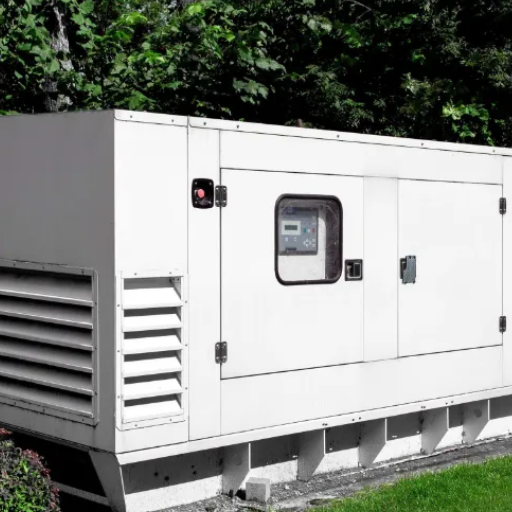
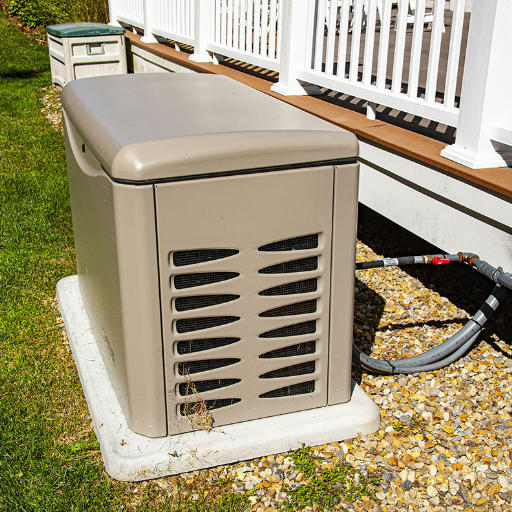
Permanent Installation Requirements for Stationary Gensets
Stationary generators for data centers are permanent infrastructure. The installation must comply with NFPA 37, NFPA 110, and the National Electrical Code (NEC) Articles 445, 700, and 701.
Concrete Pads and Anchor Bolts
Stationary generators require engineered concrete pads rated for the unit’s operating weight plus vibration isolation. Minimum pad thickness ranges from 6 to 12 inches depending on unit size, typically reinforced with rebar. Vibration isolation mounts prevent structural resonance from transmitting into the facility and surrounding soil.
Ventilation and Remote Cooling
Data center gensets are often installed in basements, parking structures, or ground-floor mechanical rooms with limited airflow. Remote radiators, intercoolers, and secondary cooling circuits mounted on roofs or upper floors are common engineered solutions. Combustion air requirements run approximately 7 to 10 CFM per kW of generator capacity. Exhaust ducting must route to the exterior with critical-grade silencers.
Sound Attenuation for Urban and Edge Data Centers
Municipal noise ordinances frequently require operational noise below 65 to 75 dB at the property line. Sound-attenuated canopies with multi-layer acoustic insulation and critical-grade exhaust silencers achieve these targets. Containerized generator data center deployments are increasingly specified for urban edge facilities where space, noise, and commissioning speed are all constrained.
Fuel Storage and Containment
Above-ground or underground double-wall tanks are standard for stationary installations. Spill containment must equal 110% of the largest tank volume. Automatic leak detection, overfill prevention, and fire-rated separation from the facility are code requirements in most jurisdictions.
For facilities requiring ultra-quiet operation in dense urban environments, explore our sound-attenuated generator solutions.
Testing and Maintenance for Stationary Data Center Generators
A stationary generator that is not tested will fail when needed. The statistics are unambiguous: 80% of generator starting failures are battery-related, and chronic under-loading causes wet stacking, a condition where unburned carbon deposits foul the engine.
Monthly Exercise Protocol
NFPA 110 Level 1 requires monthly exercise under at least 30% of rated load for 30 minutes. No-load testing is insufficient. A generator that runs without adequate load fails to reach the exhaust temperatures required to burn off carbon deposits.
Annual Load Bank Testing
Full load bank testing at 100% of rated load for 1.5 to 2 hours validates cooling systems, fuel delivery, and voltage regulation under thermal stress. This test also confirms that the generator can handle the actual facility load profile, not just a theoretical rating.
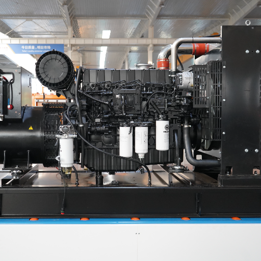
Fuel System Maintenance
Diesel fuel degrades in storage. Periodic lab analysis, water detection, and biocide treatments prevent microbial growth. Fuel polishing systems should operate continuously or on automated cycles for stationary installations.
The Cost of Skipping Tests
A hyperscale campus in the southwestern United States skipped annual load bank testing for two years because monthly no-load runs appeared normal. During a 14-hour winter storm, carbon deposits from wet stacking caused an overload shutdown within three hours. The facility required a 47,000enginerebuildandpaid47,000enginerebuildandpaid220,000 in SLA penalties to affected clients.
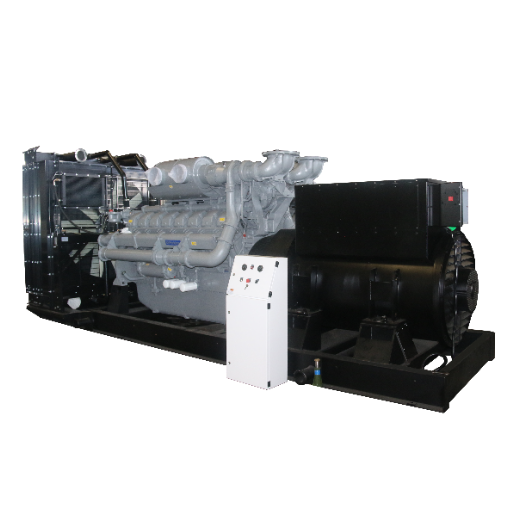
ZC Power Stationary Generator Solutions for Data Centers
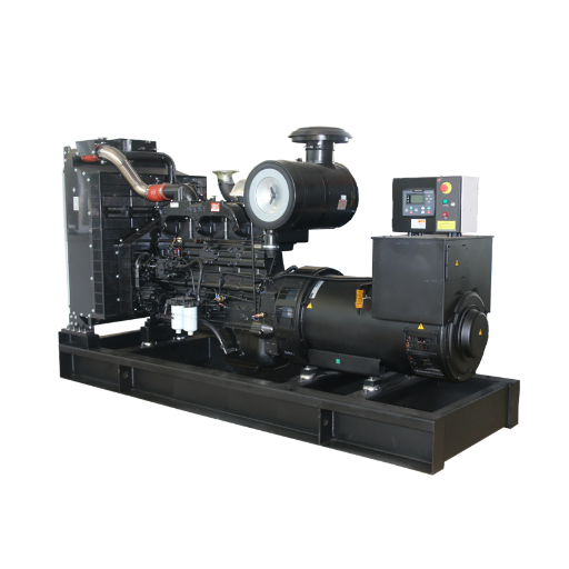
At Shandong ZC Power CO., LTD., we engineer stationary generator plants for data centers as permanent infrastructure, not commodity products. Established in 1999 and operating a 300,000-square-meter facility with a national standard testing center, we manufacture Tier III/IV stationary generator systems from 8kVA edge modules to 4,000kVA power plants.
Our factory-built stationary systems include paralleling switchgear with master-master distributed logic, eliminating single points of failure. Sound-attenuated canopies keep operational noise below 75 dB, enabling deployment in urban and edge environments with strict municipal ordinances. Our containerized generator data center solutions in 20-foot and 40-foot CSC-certified configurations arrive pre-wired and factory-acceptance tested, reducing field commissioning from weeks to under 10 days.
Every stationary generator undergoes rigorous full-load testing at our national standard testing center, including 110% overload verification, before shipment. We configure voltage, frequency, and enclosure specifications to match your destination grid, whether that is 380V/50Hz for Southeast Asia, 415V/50Hz for Africa, or 480V/60Hz for the Americas.
Our team of 80+ technical engineers provides global commissioning, startup supervision, and lifetime OEM parts supply. From the initial site assessment to final witness testing, we work as your engineering partner, not just your vendor.
Frequently Asked Questions
How fast must a data center stationary generator start?
NFPA 110 Type 10 requires that critical load be assumed within 10 seconds of utility failure. Top-tier stationary generators achieve this through block heaters, pre-lube oil pumps, and redundant starter systems.
What is the difference between N+1 and 2N redundancy?
N+1 means one spare generator beyond the minimum required capacity. Any single unit can fail without impacting the load. 2N means two completely independent power plants, each capable of carrying 100% of the facility load. Tier III requires N+1. Tier IV requires 2N or 2(N+1).
Can a data center use natural gas stationary generators exclusively?
Natural gas is viable for Tier III facilities with acceptable start-time requirements, but the 15- to 45-second start time may not meet strict Type 10 standards without dual-fuel backup. Many facilities use natural gas for primary backup with diesel as the emergency bridge.
How long should a data center stationary generator run on a full fuel tank?
Tier III facilities typically maintain 72+ hours of on-site fuel. The exact requirement depends on local codes, client SLA commitments, and grid reliability history. NFPA 110 applies a 133% buffer to calculated fuel consumption.
Do stationary data center generators need sound attenuation?
Yes, for urban and edge deployments. Municipal noise ordinances often require below 65 to 75 dB at the property line. Sound-attenuated canopies and containerized enclosures with multi-layer acoustic insulation achieve these targets.
How do I verify a stationary generator manufacturer’s ratings?
Demand ISO 8528-1 certified continuous power or prime power ratings, not marketing claims. For Tier III/IV, insist on COP or PRP ratings. Request witnessed factory acceptance testing (FAT) at 100% rated load plus 110% overload verification.
Conclusion
Stationary generators for data centers are permanent infrastructure decisions, not procurement transactions. The difference between a reliable Tier III installation and a costly outage often comes down to details: whether PUE was applied to IT load, whether the UPS topology multiplier was confirmed, whether N+1 was truly N+1 or merely an optimistic label.
The data is clear. Power failures cause nearly half of all impactful outages. Generator and integration faults remain a leading subset. The facilities that avoid these failures are the ones that engineer the entire stationary plant, from concrete pad to paralleling switchgear, with the same rigor they apply to server architecture.
If you are planning a data center build or retrofit, start with accurate load calculation. Apply PUE. Confirm your UPS topology. Size for growth and derating. Then select stationary generators for data centers from a partner capable of building, testing, and supporting the plant for its 20-plus-year lifecycle. Selecting the right stationary generators for data centers means matching ISO 8528 ratings to your Tier target, confirming UPS topology, and validating every assumption with witnessed factory testing.
Request a factory-direct quote and compliance assessment from ZC Power’s engineering team today.