
Containerized Generator Ventilation Review: Airflow Evidence to Request Before Approval
A containerized generator ventilation review should link airflow needs to fan limits, installed losses, site conditions, and thermal evidence. Ask for that chain of proof. Review it before you close the ventilation comments on a supplier’s design.
A large louver on a drawing tells you where air may pass. It doesn’t tell you how much air the installed fan can move, or whether discharged hot air will return to the inlet. Those gaps are easy to miss when the equipment schedule, drawing, and test report arrive separately.
This guide gives procurement teams and project engineers a document-based way to find those gaps. It covers a containerized diesel genset, with attention to the cooling arrangement actually selected. Use the containerized generator buying guide for the broader purchasing decision.
Key Takeaways
- Match the airflow data to the exact engine, radiator, fan, and enclosure revision.
- Trace shared air paths before adding separate airflow figures.
- Check component losses against the selected fan’s stated pressure boundary.
- Close design comments and installed thermal verification as distinct decisions.
Establish the containerized generator ventilation review baseline
Match the equipment before comparing figures
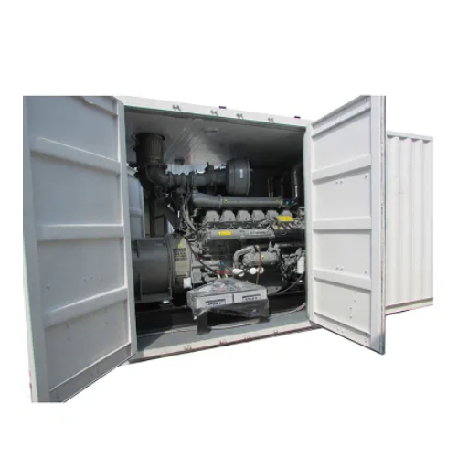
Start with a question: which exact configuration does this airflow figure describe? Record the genset reference, engine, alternator, radiator option, and fan drive. List the enclosure drawing and each part’s revision too.
Where did each figure come from? Ask the supplier to name the source and the load it describes. A family brochure may cover several options.
Ask for a clear match to the offered set.
Illustrative scenario: The bid includes a standard enclosure drawing, while the equipment schedule names a different radiator option. The airflow sheet has no option reference. Keep that comment open and request a matched submission; neither the large inlet nor the equipment’s electrical rating resolves the mismatch.
For a project inquiry, send your equipment schedule, current drawing, and site conditions to ZC Power. Include the documents still missing so the inquiry has a clear scope.
Set design conditions and responsibilities
Record the proposed duty and load. Add the design outdoor ambient, altitude, and intended door positions. What limits come from weather protection, noise control, or the site? Ask the designer which operating state governs each check.
A brochure’s ambient label may cover a different setup. Don’t treat it as proof for every enclosure. Keep the stated conditions next to the result.
The following register is a suggested buyer workflow. Assign the actual issuer and reviewer under your project responsibilities.
| Evidence requested | Expected issuer | Decision it should support |
|---|---|---|
| Selected-set heat and airflow data. | Genset application engineer. | Do the equipment and load basis match? |
| Fan capability and loss schedule. | Package and component suppliers. | Can the fan meet required flow at installed resistance? |
| Current enclosure and site drawings. | Package and site designers. | Are the air paths and surroundings shown? |
| Fan and damper sequence. | Controls designer. | Are the intended states and power sources clear? |
| Thermal verification plan. | Responsible test lead. | Are the conditions, readings, and limits agreed? |
Give each row a document number, revision, open question, owner, and closure evidence. Use the containerized generator GA drawing review alongside this register to reconcile physical openings and operating envelopes. Drawing arrows describe a proposed route; supporting calculations and tests establish what that route can support.
Reconcile combustion air, radiator flow, and enclosure heat
Trace the mounted-radiator arrangement
Combustion air enters the engine. The separate engine exhaust system carries combustion products outside. Cooling air passes through the enclosure and radiator along the designed route.
These paths do different jobs. They may still draw air through a shared opening. More ventilation won’t fix an exhaust leak.
Ask for a marked airflow diagram before comparing totals. Show the outside inlet, alternator and engine area, radiator, discharge connection, and combustion-air takeoff. Mark any auxiliary fan and the space it serves. A single label such as “ventilation airflow” leaves too much room for different interpretations.
The ventilation chapter of Cummins’ T-030 application manual, particularly sections 6.5.4–6.5.5 and 6.5.18–6.5.21, explains these configuration-dependent relationships. This is general manufacturer guidance, not approval of a particular ZC Power package.
With a set-mounted radiator, air can pick up enclosure heat before it reaches the radiator. That same stream does both jobs. Don’t just add the room heat-removal flow to the radiator flow.
Ask the engineer to show the shared path and the heat it carries. Keep the separate combustion demand clear. Mark the boundary used for the calculation.
Check what remains with remote cooling
A remote radiator moves coolant heat rejection away from the enclosure. It doesn’t remove heat released by the engine surfaces, alternator, or other equipment inside. The enclosure still needs a reviewed heat-removal arrangement, which may use separate fans. Identify their electrical loads and how they operate when normal power is unavailable.
| Review boundary | Evidence to request |
|---|---|
| Air entering the enclosure. | What total intake is needed? Show any shared paths. |
| Heat released inside. | Supply the heat data for the set at the stated load. |
| Coolant heat rejected elsewhere. | Show the remote-cooling design and its own assumptions. |
| Air leaving the enclosure. | Show the outlet route, fan duty, and resistance basis. |
Align units and assumptions
Is volume flow actual, or stated at standard conditions? Record that basis with the air temperature and density. Keep mass flow, volume flow, and pressure units clear.
Two tables can show similar numbers yet describe different conditions. Ask for a common basis before you compare them.
For a heat-balance calculation, ask which heat enters the air stream, which temperature rise is allowed, and where the inlet temperature is measured. The reviewer needs those inputs and the engineer’s explanation, rather than a bare answer. Coordinate the resulting requirements with the wider industrial generator installation guide and the project mechanical design.
Check the fan operating point, louvers, and pressure budget
Compare airflow at the relevant resistance
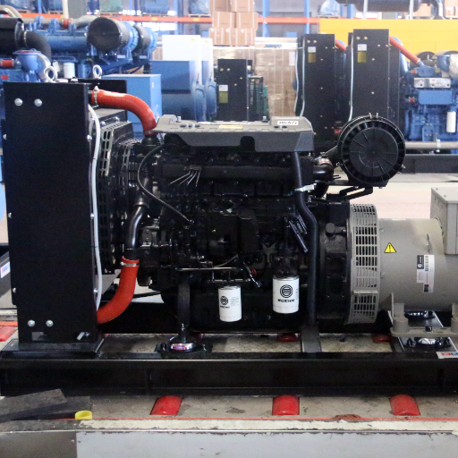
A free-air fan rating does not show delivered flow through the installed enclosure. Request the selected fan curve or the package maker’s permitted external restriction, together with the airflow requirement and operating conditions. The supplier should show how the selected duty is supported. A statement that the fan is “large enough” leaves the central comparison unanswered.
First establish the pressure boundary. A bare-fan curve covers a different scope from a package’s external static pressure allowance. What does each include?
Ask whether the radiator core and other internal losses are already covered. Don’t count the core twice. Don’t leave out the external duct.
Both errors distort the check.
If curves are supplied, ask the designer to mark the operating point. Check that the pressure terms and test conditions match. Does the supplier give a package limit instead? Ask for the external loss calculation at required flow.
Compare that loss with the stated limit. Don’t use a generic allowance from another model or a manual example. Keep the source of the limit in the record.
Build a component loss schedule
Use one schedule for the complete reviewed path. Identify each selected size and the data behind its loss; don’t add unrelated catalogue values measured at different flows.
| Component or path | Data needed at the selected duty | Boundary check |
|---|---|---|
| Intake louver. | Give the selected size, free area, and pressure-loss curve. | Which area defines flow velocity? |
| Mesh or filter, if fitted. | Name the part and its clean or service condition. | Is its loss separate or included? |
| Acoustic splitter. | Show its shape and supplier loss data. | Is this the reviewed acoustic package? |
| Duct, transition, and bends. | Show the sizes and calculation basis. | Does this cover the full discharge route? |
| Damper and outlet hood. | State their working positions and loss data. | Does this match the final assembly? |
Free area is useful, but it isn’t the delivered airflow. For example, Safe-Air’s sand-louver table lists 53% free area for its V-DEM-08 at 48 by 48 inches. That is a size-specific component example, not a default percentage for generator containers or a recommended ZC component.
You still need the selected louver’s loss data at the proposed duty. Check the exact size first. A percentage for another size won’t close that gap.
Does each curve use face velocity or velocity through free area? Record the answer. Ask the supplier to show the area used to turn airflow into velocity.
Then another reviewer can repeat the check. A loss value may look sound yet come from the wrong part of a catalogue.
Keep acoustic and maintenance assumptions visible
Illustrative scenario: An acoustic splitter is added after the initial fan review. The old loss schedule covers only the original intake and outlet. Reopen the affected rows and request revised component data and a fan check; an unchanged enclosure outline doesn’t mean the air path is unchanged.
Ask the supplier to reconcile that table before treating the revised acoustic proposal as closed. Use the separate guide to verify generator noise claims for sound evidence, while retaining the airflow check here.
If filters or sand-control devices are proposed, record their assumed service condition and maintenance access. Request the designer’s treatment of increasing restriction. A documented project allowance is reviewable; an unexplained universal margin isn’t. Keep the original and revised schedules together so the reason for reopening the decision stays visible.
Check hot-air recirculation, weather, and controls
Extend the review beyond the container
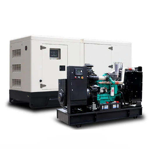
Air can leave the enclosure and return to its intake because of the surrounding layout. Mark the inlet and discharge on the current site plan. Show walls, screens, roofs, nearby equipment, and other generator sets.
Which wind conditions did the designer use? Record them on the plan. The container drawing alone can’t show all these surroundings.
Distinguish outdoor ambient from air already warmed inside the enclosure. Caterpillar’s November 2016 ambient-capability paper describes how enclosure restriction and preheating affect ambient capability. A temperature recorded at the radiator inlet should not be relabeled as outdoor ambient.
Ask how the layout review addresses hot discharge returning to the intake or entering adjacent equipment. Ask the site designer to explain the review method. What risks still need a closer check?
Use that answer to decide if more analysis is needed. This worksheet gives no universal clearance. It doesn’t require CFD for every site.
Check rain and sand provisions together with airflow. A hood, screen, or weather louver may change the path and resistance already reviewed. Identify the intended operating position of doors and removable panels. Evidence from a test with doors open needs an explanation before it supports normal closed-door operation.
Review start, run, stop, and failure states
Request a sequence covering dampers and auxiliary ventilation fans. Where does each actuator and fan get power? Is that source available when normal power fails?
Ask how the controls establish that the path is ready. What proves that a damper reached its commanded state? Record what happens if it fails to get there.
Review post-run heat and any proposed fan run-on with the controls designer. Engine shutdown may leave heat to remove. Don’t assume that every ventilation need ends at once.
One generic timer won’t suit every design. Ask which equipment data support the chosen sequence and which conditions it covers.
Assign site-layout questions to the site designer and sequence questions to the controls issuer. Cross-reference the drawing revisions in the register. This prevents a well-documented package from receiving an open-ended acceptance for surroundings or control states that were never assessed. Close each comment only for the scope its evidence actually covers.
Close the ventilation review with thermal and revision evidence
Separate package evidence from installed verification
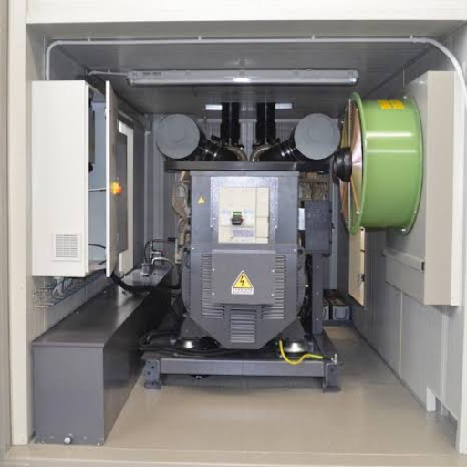
A factory load-bank report can show useful electrical test results. That alone doesn’t prove cooling for the installed layout. Which enclosure and outlet parts were tested? Ask for the air paths and test conditions too.
Track three distinct decisions: design review, factory package testing, and site thermal verification. State which one the report supports. Don’t let one signed report close all three by default.
Illustrative scenario: A factory report covers the enclosure without the final outlet hood. The report need not be called a failed test. Record the configuration difference, ask for its effect on the pressure budget, and leave the relevant installed-cooling question open until the responsible reviewer accepts supporting evidence.
Agree what a thermal record must show
Before a test, request the protocol and selected equipment limits. The Cummins field-test guidance in section 6.5.19 emphasizes documented load, ambient conditions, and stabilized temperatures. A fixed elapsed time alone does not demonstrate that temperatures have stabilized, nor does a mild-weather run automatically prove operation at the design extreme.
| Test record field | Review question |
|---|---|
| Equipment and drawing revisions. | Does the tested setup match the offered or installed package? |
| Electrical load and relevant power factor. | What duty did the test show? |
| Outdoor conditions and site elevation. | How do these compare with the design basis? |
| Doors, louvers, dampers, and hoods. | Were they in their intended operating states? |
| Probe locations and instrument details. | Which temperature and pressure does each reading show? |
| Temperature trends and stabilization basis. | Do the records show a stable condition? |
| Acceptance limits and deviations. | Which equipment limits were used? What remains open? |
Keep outside-air readings separate from engine intake air and radiator inlet air. Label the specified coolant points too. Ask the test lead to mark each probe on a drawing. Request the instrument accuracy or calibration records needed for the test plan.
Where was each reading taken? A column headed “temperature” won’t answer that question. The location is part of what gives the reading meaning.
Does the test differ from the design basis? Ask the responsible engineer for a written explanation. Don’t invent a temperature correction or use another engine’s limit.
A run with no alarm isn’t a complete thermal record. State what the test proves and what it leaves open.
Record a scoped decision and change trigger
Use clear statuses such as “hold,” “evidence received,” and “accepted for stated scope.” Name the reviewer, reference the accepted revisions, and carry unresolved site work into commissioning. This is a suggested tracking method, not a certification scheme.
Reopen affected checks when the radiator, fan, louver, acoustic path, duct, outlet hood, site layout, or control sequence changes. Preserve superseded evidence. A controlled record lets the next reviewer see what was established and which change requires fresh support, without repeating the entire project review.
Frequently asked questions and project handoff
Can a louver size or CFM-per-kW rule prove adequate ventilation?
No. Opening dimensions and generic airflow ratios do not establish delivered airflow through the selected enclosure. Request equipment-specific requirements, louver free-area and loss data, the complete resistance schedule, and the fan check. Use a rule of thumb only as a preliminary prompt for engineering review, never as the approval record.
Should radiator airflow and room heat-removal airflow simply be added?
Not automatically. With a mounted radiator, the same air stream may remove enclosure heat before reaching the radiator. Ask the engineer to mark the shared path, identify the heat included in each calculation, and reconcile combustion demand. Separate airflow labels do not necessarily describe separate streams that should be summed.
Does a remote radiator remove the enclosure ventilation requirement?
No. Remote coolant heat rejection still leaves heat from equipment inside the enclosure. Request a heat balance for that remaining load and a defined ventilation arrangement. Review any auxiliary fans, their resistance, electrical supply, and control sequence against the selected equipment and site conditions rather than assuming the enclosure needs no airflow.
Does a factory load-bank report prove site cooling?
Only the report’s documented scope can be assessed. Check load, ambient conditions, enclosure configuration, probe locations, and stabilized readings. Then compare them with the installed design. Missing hoods, different surroundings, or untested control states may require further evidence; an electrical pass alone does not close every installed thermal question.
Which changes require a fresh ventilation review?
Recheck changes that affect airflow requirements, pressure losses, inlet temperature, or operating states. Examples include a radiator substitution, added acoustic treatment, revised louvers, new discharge ducting, nearby walls, and altered damper controls. The responsible reviewer should identify affected evidence and record the decision against the new revisions, retaining the earlier record.
The goal is a traceable handoff: matched equipment data, a reconciled air path, a supported pressure budget, and thermal evidence with clear limits. In the hood scenario, the next action is a documented technical response to the changed configuration.
For your project inquiry, send ZC Power the selected equipment references, current site layout, airflow documents, and open questions. Keep the responsible designer’s decisions and remaining site verification visible as the project moves from submission to installation.


