Heavy Duty Diesel Generator Installation: Complete Industrial Guide
A heavy duty diesel generator installation is a multi-system project that extends far beyond unloading the genset. It demands coordinated civil, mechanical, electrical, and commissioning work, all governed by NFPA 37, NFPA 70 (NEC), NFPA 110, and the local Authority Having Jurisdiction (AHJ).
In 2024, a 1,500kW standby genset arrived on a construction site in Ghana. The pad was 400 mm shorter than the skid, the cable trench ran directly beneath the exhaust outlet, and the crane could not reach the designated offload point. The delays cost the EPC contractor $67,000 in standby labor and pushed the project handover by two weeks. Most installation failures don’t begin on site; they begin with a rushed site assessment.
This guide explains how to plan and execute a heavy duty diesel generator installation from the first site walk to final acceptance testing. It covers foundation design, ventilation calculations, fuel and exhaust systems, electrical termination, ATS integration, commissioning, and realistic 2026 costs for industrial units from 500kW to 4,000kW.
Key Takeaways
- Equipment is typically 60–70% of total project cost; foundation, fuel, electrical, and commissioning can add 25–50%.
- The concrete pad must support the genset’s wet weight plus a 25% dynamic margin and must be isolated from the building foundation.
- Generator room air inlet openings should be at least 1.5 times the radiator outlet area to prevent overheating.
- NFPA 110 requires acceptance testing before an emergency power supply system can be declared operational.
- Factory-direct engineering review, containerized delivery, and remote-site commissioning support reduce risk on international projects.
Need installation support for your project? Contact a ZC Power engineer for site review, foundation guidance, and factory-direct commissioning.
Why Heavy Duty Diesel Generator Installation Is Different
Industrial Scale Changes Everything
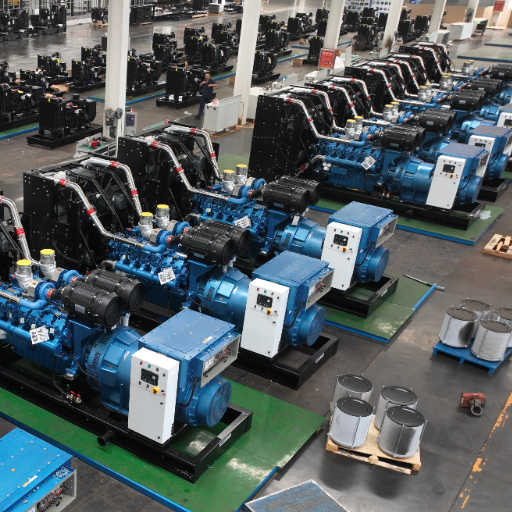
A 20kW residential standby set weighs less than a pickup truck. A 2,000kW industrial genset can weigh 18,000 kg, require a dedicated crane, and need a reinforced concrete pad engineered for dynamic loads. The complexity of a heavy duty diesel generator installation scales with kW rating, not just physical size.
Industrial units also differ in duty cycle. A standby genset runs a few hundred hours per year. A prime-power unit in mining or oilfield service may run 6,000–8,000 hours annually. That difference affects ventilation sizing, fuel-system capacity, exhaust routing, and service access. For a clear explanation of how duty-cycle ratings influence installation requirements, see our guide to prime vs. standby power.
Multi-Discipline Coordination
A complete installation involves civil contractors for the pad and trenches, mechanical contractors for exhaust and fuel piping, electrical contractors for cabling and switchgear, and commissioning engineers for testing and documentation. Permits must be secured before concrete is poured, and the AHJ must inspect critical stages. When these trades work in sequence without a shared plan, small errors compound.
Factory-Direct vs. Field-Integrated Systems
Pre-configured containerized or canopy gensets arrive with most systems integrated. Open skid units require more field assembly. Factory-direct manufacturers can supply installation drawings, wiring diagrams, and certified foundation templates before the unit ships. That documentation eliminates guesswork and helps the contractor prepare the site correctly the first time.
Pre-Installation Planning for Heavy Duty Diesel Generator Installation
Every successful heavy duty diesel generator installation starts with a detailed generator installation checklist. The checklist should cover site selection, load review, permits, crane logistics, and trade coordination before the genset ships.
Heavy Duty Diesel Generator Installation Checklist
- Confirm site soil bearing, drainage, flood plain, and crane access.
- Complete electrical load review with motor starting and future expansion margin.
- Secure permits and schedule AHJ inspections before concrete is poured.
- Coordinate civil, mechanical, electrical, and commissioning trades.
- Prepare pad dimensions, anchor-bolt patterns, and vibration isolation details.
- Size ventilation, exhaust, fuel, and ATS requirements using manufacturer data.
- Plan acceptance testing and handover documentation in advance.
Site Selection Criteria
The best installation sites share several characteristics:
- Stable, well-drained soil that can support the pad and crane outriggers.
- Flood clearance above the 100-year flood plain or protected by drainage.
- Noise exposure directed away from residential areas, hospitals, or offices.
- Prevailing wind that carries exhaust away from building intakes.
- Crane access with clear approach, offload, and placement paths.
- Security to prevent unauthorized access, fuel theft, or vandalism.
Indoor installations add constraints: ceiling height, load-bearing floors, fire-rated separation, and ventilation duct routing. Outdoor installations require weatherproof enclosures, noise control, and protection from solar heating in hot climates.
Load and Electrical Review
Before the pad is poured, the electrical team must confirm:
- Total running load and power factor.
- Largest motor starting surge and voltage dip limits.
- Future expansion margin, typically 20–25%.
- Required voltage, frequency, and phase configuration.
- Whether the ATS will be service-entrance rated or downstream of the main disconnect.
Skipping this review leads to undersized cables, inadequate breaker coordination, and gensets that cannot start critical motors. Our complete heavy-duty diesel generator buying guide explains how to match unit rating to site load.
Permits and Code Review
Relevant codes for most projects include:
- NFPA 37, stationary combustion engine installation.
- NFPA 70 (NEC), electrical installation, grounding, and bonding.
- NFPA 110, emergency and standby power systems, including acceptance testing.
- Local fire, noise, and environmental ordinances, often more restrictive than national codes.
The AHJ may require stamped drawings, fire-rated barriers, emissions compliance documentation, and inspection sign-offs before energizing the system. Starting the permit process early prevents schedule surprises.
Logistics and Crane Plan
A 1,000kW genset in a sound-attenuated enclosure can exceed 10,000 kg. The crane plan must account for:
- Unit weight plus lifting beam and rigging.
- Radius from crane center to placement point.
- Ground bearing pressure under outriggers.
- Clearance from overhead lines, structures, and other equipment.
- Offload sequence and temporary storage if the pad is not ready.
Foundation and Mounting Requirements
Generator Foundation Requirements: Concrete Pad Specifications
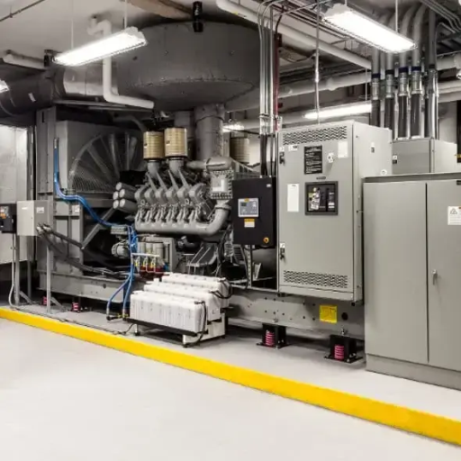
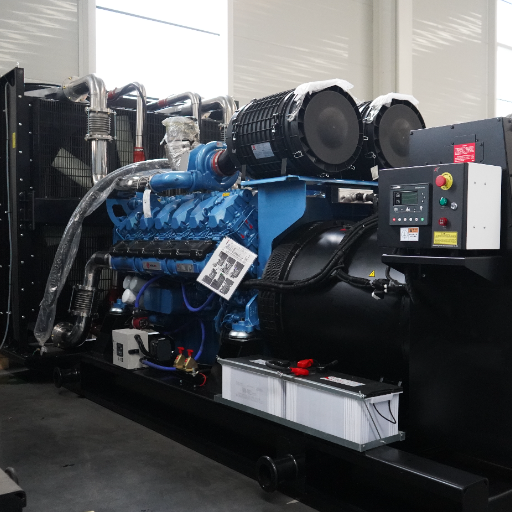
The foundation is one of the most critical and least forgiving parts of a heavy duty diesel generator installation. The following generator foundation requirements apply to most skid-mounted industrial gensets:
- Dimensions: pad should extend at least 300 mm beyond the genset skid on all sides.
- Thickness: commonly 200–400 mm for skid-mounted units, depending on soil bearing and dynamic loads.
- Reinforcement: steel rebar mesh to control cracking under vibration.
- Anchor bolts: embedded or drilled and epoxy-set, sized to manufacturer torque specs.
- Leveling: surface flatness within ±3 mm per meter.
- Isolation: the foundation must not be connected to the main building slab to prevent vibration transmission.
Load Calculations
The pad must support the genset wet weight plus a 25% margin for vibration and dynamic loading. For example, a 1,000kW silent canopy genset weighing 9,500 kg with a 1,500 kg base fuel tank needs the foundation designed for approximately 14,000 kg static-equivalent load. A geotechnical engineer should verify soil bearing capacity and recommend any pilings or mat foundations for poor soils.
Vibration Isolation
Vibration isolators sit between the genset skid and the foundation. Common options include:
- Rubber/cork pads for small to mid-size units.
- Spring isolators for large units or rooftop installations.
- Inertia blocks, a separate concrete block on isolators that adds mass and dampens vibration.
Rooftop installations require spring isolators with high static deflection and careful structural review of the building frame. Flexible electrical conduit and fuel lines must be used near the unit to absorb movement.
Clearance, Accessibility, and Safety Layout
Proper clearances are a code requirement and a service requirement for any heavy duty diesel generator installation.
NEC and NFPA 37 Clearance Requirements
Clearance rules vary by enclosure rating and local code, but common minimums for non-SWRI-rated units include:
- 5 ft (1.5 m) from non-fire-rated walls or combustible surfaces.
- 3 ft (0.9 m) from one-hour fire-rated walls.
- No operable windows or doors within 5 ft of the exhaust or air intake.
- 5 ft overhead clearance above the unit.
- Service access aisles at least 1 m wide on all sides.
SWRI-rated enclosures allow reduced clearances because the enclosure itself is fire-tested. Always verify the manufacturer’s listed clearances for the specific model.
Service Access
Maintenance technicians need access to the radiator, alternator, control panel, battery, filters, and oil fill points. Placing the genset against a wall or in a corner may satisfy code clearance but make routine service difficult. Aisle widths and removable panels should be planned around the largest replaceable component, often the radiator or alternator.
Fire and Explosion Safety
Fuel storage must meet separation distances from buildings and ignition sources. Indoor installations require fire-rated separation between the generator room and the rest of the building. They also need automatic fire suppression or gas-extinguishing systems, plus ventilation interlocks that close dampers during discharge. Exhaust systems must terminate away from combustible roofs and fresh-air intakes.
Generator Room Ventilation Design
Generator Room Ventilation Requirements: Heat Rejection and Airflow
Proper generator room ventilation requirements are what keep a heavy duty diesel generator installation from overheating. A diesel genset rejects roughly one-third of fuel energy as waste heat. In an enclosed room, this heat must be removed or the engine will overheat, derate, or shut down. Ventilation airflow must handle:
- Radiator heat from engine coolant.
- Engine radiation and alternator losses.
- Combustion air required by the engine.
Ventilation Calculation Formula
A common sizing shortcut for diesel generator rooms is:
C = 0.078 × P × ΔT
Where:
- C = required fresh air volume in m³/s
- P = rated engine power in kW
- ΔT = permissible room temperature rise in °C
For a 1,000 kW genset with a permitted 10 °C room rise, the calculation gives 7.8 m³/s (approximately 16,500 CFM). This is a planning estimate; the final design should use the engine manufacturer’s heat-rejection data and account for duct losses, louvre restriction, and altitude derating.
Louvre and Duct Sizing
Air inlet openings should be at least 1.5 times the area of the radiator outlet to keep static pressure low. A practical rule of thumb is 0.15 m² of free louvre area per 100 kW of generator power. Hot air should be ducted directly outside and never allowed to recirculate into the intake.
Combustion Air Supply
Combustion air is separate from cooling air. Modern turbocharged diesels require roughly 6–8 m³ of air per kW-hour. In tightly sealed rooms, a dedicated combustion-air duct may be needed to prevent the room from going negative and drawing exhaust or fumes back inside.
Fire Dampers and Gas Extinguishing Interlocks
If the room has a gas fire-extinguishing system, supply and exhaust dampers must close automatically during discharge and reopen afterward for purge ventilation. Fan controls should be interlocked with the fire alarm panel.
Exhaust System Installation
Exhaust routing is often overlooked during a heavy duty diesel generator installation, yet backpressure and routing mistakes can reduce output and create safety hazards.
Exhaust Pipe Sizing and Backpressure
Exhaust piping must be sized to keep backpressure within the engine manufacturer’s limit, typically 5–10 kPa for turbocharged engines. Undersized pipe, too many bends, or long horizontal runs increase backpressure, reduce power, and raise exhaust temperatures. A 1,000kW genset may need 200–250 mm diameter piping depending on length and bends.
Flexible Bellows and Support
A flexible exhaust bellows absorbs vibration and thermal expansion between the engine and rigid piping. The rigid pipe must be independently supported so its weight does not rest on the engine turbocharger or manifold. Hangers should allow thermal movement.
Insulation and Routing
Exhaust piping must be insulated where it passes through walls, ceilings, or near combustible materials to prevent fire. Piping should slope back toward the engine or to low-point drains to remove condensate. The termination should be:
- Above the roof line.
- Away from building air intakes, windows, and pedestrian areas.
- Fitted with a rain cap or bird screen.
Emissions Aftertreatment
EPA Tier 4 Final and EU Stage V engines require diesel oxidation catalysts (DOC), diesel particulate filters (DPF), selective catalytic reduction (SCR), or combined systems. These add backpressure, require DEF (urea) supply for SCR, and need service access. Installation drawings must show catalyst placement, sensor ports, and maintenance clearance.
Fuel System Installation
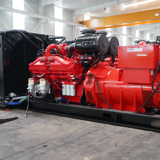
Fuel system design can make or break a heavy duty diesel generator installation, especially for sites where refueling access is limited or runtime requirements are long.
Day Tank and Main Tank Sizing
The day tank supplies fuel directly to the engine and returns excess fuel from the injection system. Typical sizing allows 8–24 hours of runtime at rated load. The main storage tank is sized for the desired refueling interval, commonly 48–96 hours for standby applications or weekly delivery for prime power.
A 1,000kW diesel genset at full load consumes approximately 250–280 liters per hour. A 24-hour day tank therefore holds 6,000–7,000 liters. Return fuel flow can equal engine consumption, so the day tank must handle both supply and return without overheating the fuel.
Fuel Transfer Pumps and Piping
Fuel lines should use flexible connections near the genset to absorb vibration. Key design points:
- Shutoff valves at the tank and at the engine.
- Leak containment and secondary containment for tanks and piping.
- Properly sized transfer pumps with automatic level control.
- Fuel lines sloped to drain back to the tank where possible.
- Avoid galvanized pipe; diesel fuel reacts with zinc coatings.
Fuel Quality and Filtration
Target fuel cleanliness of ISO 18/16/13 or cleaner. Install water separators and particulate filters between the tank and engine. Diesel fuel begins degrading after 6–12 months without treatment, so standby units need periodic fuel testing, biocide treatment, or fuel polishing.
Underground vs. Above-Ground Storage
Above-ground tanks are easier to inspect and maintain but require secondary containment and fire-rated separation. Underground tanks save space and reduce fire exposure but need corrosion protection, leak detection, and costly remediation if they fail. Local environmental regulations often dictate the choice.
Electrical Connections and Grounding
Electrical termination is where a heavy duty genset installation moves from mechanical work to live-power safety.
Generator Output Cabling
Generator output cables run from the main-line circuit breaker (MLCB) to the ATS or switchgear. Cable sizing must account for:
- Full-load current at rated voltage and power factor.
- Voltage drop, typically limited to 2–3%.
- Ambient temperature and grouping derating.
- Fault-current withstand for short-circuit conditions.
For a 1,000kW generator at 400V three-phase, full-load current is approximately 1,800A. Multiple parallel cables per phase are usually required.
Grounding and Bonding
NFPA 70 Article 250 requires the genset frame, enclosure, fuel tank, and exposed conductive parts to be bonded and grounded. Key elements:
- Equipment grounding conductor sized to the phase conductors.
- Grounding electrode conductor to the building’s grounding system.
- Neutral-to-ground bonding at the generator for separately derived systems, or at the ATS depending on system design.
- Ground-fault protection coordination for large units.
Improper grounding creates shock hazards, equipment damage, and nuisance tripping.
Control and Monitoring Wiring
Low-voltage control wiring for start signals, ATS position indication, and remote monitoring must be run in separate conduits from high-voltage power cables. Shielded cable may be needed near variable-frequency drives or other noise sources.
Protection Relay and Breaker Coordination
Generator breakers, ATS switches, and main distribution breakers must be coordinated so a fault downstream trips only the nearest protective device. Short-circuit studies and arc-flash hazard labeling are required for many industrial installations under NFPA 70E and NEC 110.16.
ATS Transfer Switch Installation and Switchgear Integration
ATS transfer switch installation determines how cleanly the building load moves between utility and generator power.
Automatic Transfer Switch Placement
The ATS transfers load between utility and generator power. Service-entrance rated ATS units include the utility disconnect and serve as the main service entrance. Non-service-entrance ATS units sit downstream of the main breaker. The choice affects grounding, metering, and utility interconnection requirements.
Control Wiring Between Generator and ATS
A typical installation requires:
- Two-wire start circuit from ATS to generator to initiate auto-start on utility failure.
- Three-wire position indication from ATS to generator to signal normal/emergency status.
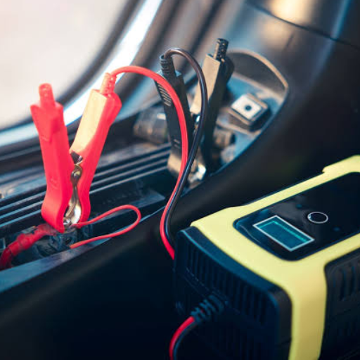
- Battery charger and block heater circuits powered from the appropriate source.
A licensed electrician should make these connections and verify polarity, voltage, and function.
Load Shedding and Priority Schemes
Large facilities may not have enough generator capacity to serve every load. Load-shedding controllers disconnect non-critical loads during an outage to protect voltage and frequency stability. Priority schemes must be documented and tested.
Parallel Operation Basics
Multiple gensets can operate in parallel to increase capacity or redundancy. Parallel systems require compatible voltage regulators, governors, synchronizers, and protective relays. Installation must include reverse-power, overcurrent, and differential protection. This guide focuses on single-unit installation; parallel systems require specialized engineering.
Noise Control and Environmental Considerations
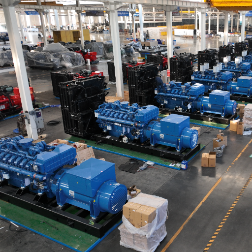
Noise and emissions planning should start early in a heavy duty diesel generator installation because they often dictate enclosure selection, setback distances, and permit approvals.
Sound-Attenuated Enclosures
Urban hospitals, data centers, and commercial sites often require noise levels below 75 dB(A) at 7 meters. Factory-built silent canopies use acoustic insulation, labyrinth air intakes, and residential-grade silencers to meet these targets. The enclosure must still allow adequate airflow and service access.
Acoustic Louvres and Barriers
For indoor installations, acoustic louvres reduce noise breakout through ventilation openings. Outdoor sites may need perimeter walls or earthen berms. Noise propagation should be modeled during design, not after complaints arise.
Emissions Compliance
Engine emissions must comply with local regulations. In the United States, EPA Tier 4 Final applies to many new non-emergency units above 560 kW. In the European Union, Stage V applies to many portable and mobile generators. Emergency standby units often have different requirements than prime-power units. Emission control equipment must be sized, installed, and maintained per the engine manufacturer’s instructions.
Commissioning and Acceptance Testing
Commissioning is the final quality gate of any heavy duty diesel generator installation and the step that proves the system will perform during an outage.
Pre-Start Verification
Before the first start, verify:
- Oil, coolant, and fuel levels.
- Battery voltage and charger operation.
- Belt tension and alignment.
- Exhaust and ventilation connections.
- Fuel, coolant, and exhaust leaks.
- Electrical terminations and torque values.
- Grounding and bonding continuity.
- Control panel settings and safety shutdowns.
No-Load and Loaded Test Procedure
A typical commissioning load test follows a stepped profile:
- No-load run: verify voltage, frequency, oil pressure, and coolant temperature.
- 25% load for 30 minutes: monitor stability and temperatures.
- 50% load for 30 minutes: watch for smoke, vibration, or abnormal noise.
- 75% load for 60 minutes: confirm cooling system keeps pace.
- 100% load for 30–120 minutes: verify full-load performance and exhaust temperature.
For Level 1 emergency systems, NFPA 110 also requires a 4-hour continuous load test every 36 months at full rated kW.
ATS Functional Test
Simulate a utility outage at the ATS to verify:
- Generator auto-start within required time.
- ATS transfers load to emergency source.
- Voltage and frequency remain stable.
- Utility restoration triggers retransfer after cooldown.
- Generator shuts down and returns to standby.
For service-entrance rated ATS units, a utility technician may need to open the incoming feed for the test.
NFPA 110 Acceptance Testing
NFPA 110 requires acceptance testing for new emergency power supply systems before they are declared operational. For a detailed breakdown of start-time classifications and what Type 10 means for your project, see our guide to NFPA 110 Type 10 requirements.
The test must document start time, transfer operation, voltage and frequency stability, safety shutdown function, and full-load performance. Results are submitted to the AHJ as part of the final inspection package.
Handover Documentation
The commissioning package should include:
- As-built drawings and single-line diagrams.
- Factory and site test reports.
- O&M manuals for the genset, ATS, and switchgear.
- Warranty certificates and registration documents.
- Recommended spare parts list.
- Operator training records.
Proper documentation protects warranty coverage and simplifies future inspections. Our guide to generator load bank testing explains how to document ongoing testing after commissioning.
Installation Cost and Timeline
Cost Breakdown by Component
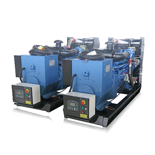
Equipment is typically 60–70% of total heavy duty diesel generator installation cost. The table below shows 2026 planning ranges for heavy-duty industrial installations in standby or light prime service.
| Generator Size | Equipment | Installation & Labor | ATS/Switchgear | Foundation/Fuel | Permits/Commissioning | Total |
|---|---|---|---|---|---|---|
| 500 kW | 45,000–45,000–85,000 | 12,000–12,000–22,000 | 5,000–5,000–12,000 | 4,000–4,000–10,000 | 2,000–2,000–5,000 | 68,000–68,000–114,000 |
| 1,000 kW | 90,000–90,000–150,000 | 20,000–20,000–35,000 | 10,000–10,000–20,000 | 8,000–8,000–18,000 | 3,000–3,000–7,000 | 131,000–131,000–230,000 |
| 2,000+ kW | 180,000–180,000–400,000+ | 40,000–40,000–80,000 | 20,000–20,000–45,000 | 15,000–15,000–35,000 | 5,000–5,000–12,000 | 260,000–260,000–572,000+ |
Regional factors such as labor rates, import duties, freight, and local compliance can shift these ranges by 15–55%. For context on lifetime operating costs beyond installation, including downtime risk and total cost of ownership, see our guide to standby generator ROI. You can also review our heavy duty diesel generator fuel consumption guide for runtime fuel estimates.
Typical Timeline
| Phase | Duration |
|---|---|
| Site assessment and electrical review | 1–2 weeks |
| Permits and foundation construction | 4–8 weeks |
| Equipment manufacturing and delivery | 12–70 weeks |
| Mechanical and electrical installation | 2–6 weeks |
| Commissioning and acceptance testing | 3–7 days |
Lead Time Planning (2026)
Lead times vary sharply by manufacturer tier:
- Tier 1 Western brands (Cummins, Caterpillar, MTU, Kohler): 40–100 weeks for units above 1,000 kW.
- Certified factory-direct manufacturers: 18–30 weeks for standard configurations.
- Budget assemblers: 4–12 weeks, often with limited documentation and support.
Planning the installation in parallel with equipment procurement prevents the site from sitting idle while waiting for delivery.
Common Installation Mistakes to Avoid
Most heavy duty diesel generator installation failures are not caused by the genset itself; they are caused by predictable planning errors that could have been caught early.
Inadequate Site Assessment
Skipping a detailed site walk is the most expensive mistake. Check soil conditions, crane access, noise exposure, exhaust routing, and utility locations before finalizing the layout.
Undersized Foundation or Pad
A pad that supports static weight but not dynamic vibration will crack. Always design for wet weight plus a 25% margin and isolate the foundation from the building slab.
Poor Ventilation Design
Undersized louvres or recirculating hot air cause high-temperature shutdowns. Size inlets at 1.5 times radiator outlet area and use manufacturer heat-rejection data.
Incorrect Exhaust Routing
Exhaust terminating near air intakes, windows, or pedestrian areas creates safety and odor problems. Route above roof lines and away from building openings.
Fuel System Oversights
Undersized day tanks, lack of water separation, or galvanized piping lead to no-start failures and injector damage. Size for both supply and return fuel flow.
Missing Acceptance Documentation
NFPA 110 and most AHJs require documented acceptance testing. Skipping this step can delay occupancy permits and void warranty coverage if failures occur later.
For a deeper look at matching generator size to real load, see our heavy duty diesel generator sizing guide.
Installation in Extreme Environments
Every heavy duty diesel generator installation in extreme environments needs tailored mitigation for dust, cold, humidity, salt, or altitude.
High Dust and Desert Sites
Desert mining and construction sites load air filters rapidly. Install pre-cleaners or cyclonic intakes, sealed enclosures, and plan for daily air-filter inspection. Position air intakes away from dust-generating equipment and prevailing dust-laden winds.
Cold Climates
Cold weather thickens oil, reduces battery capacity, and makes starting difficult. Install block heaters and battery warmers, use cold-weather oil with the correct viscosity, and maintain coolant freeze protection well below the lowest expected temperature. Fuel must be treated for cold-flow properties.
Tropical and Coastal Sites
Humidity and salt accelerate corrosion and microbial growth in fuel tanks. Apply anti-corrosion coatings, use dehumidifiers or heaters inside enclosures, drain water from fuel tanks frequently, and check insulation resistance more often than in dry climates.
High Altitude
At altitude, air density drops and engine output derates approximately 3–4% per 300 m above sea level. Turbocharged engines recover some of this loss, but installations above 1,500 m require derating calculations, larger airflow openings, and possible injector or turbocharger adjustments.
ZC Power Installation Support
ZC Power supports every stage of a heavy duty diesel generator installation with factory-direct engineering review, technical documentation, and global logistics.
Factory-Direct Engineering Review
As a source manufacturer established in 1999, ZC Power provides site layout and foundation review before shipment. Our engineering team checks pad dimensions, anchor-bolt patterns, ventilation requirements, and exhaust routing against the specific genset model.
Custom Canopy and Container Options
We build open, silent, trailer, and containerized gensets from 100kVA to 4,000kVA. A containerized diesel generator arrives with fuel tanks, exhaust silencers, ventilation, and electrical termination points pre-integrated. That reduces field assembly time and installation risk on remote sites.
Technical Documentation
Every unit ships with installation manuals, wiring diagrams, single-line drawings, and test certificates. Because we design and assemble the gensets, the documentation matches the exact build, including engine, alternator, controller, and options.
Global Export and Remote Site Logistics
ZC Power has shipped generators to more than 100 countries. We understand the documentation, customs, and logistics challenges of maintaining equipment in remote locations. When urgent parts or commissioning guidance is needed, we can air-freight components and provide remote engineering support.
Frequently Asked Questions
How much does it cost to install a heavy duty diesel generator?
For 2026, a 500 kW industrial diesel generator installation typically costs 68,000–68,000–114,000 total, including equipment. A 1,000 kW unit ranges from 131,000–131,000–230,000, and a 2,000+ kW unit can reach 260,000–260,000–572,000 or more depending on site conditions and regional labor rates.
What size concrete pad does a diesel generator need?
The concrete pad should extend at least 300 mm beyond the genset skid on all sides, be 200–400 mm thick depending on load, and support the genset wet weight plus a 25% dynamic margin. The foundation must be isolated from the building slab to prevent vibration transmission.
How do you calculate generator room ventilation?
A planning formula is C = 0.078 × P × ΔT, where C is airflow in m³/s, P is rated kW, and ΔT is permissible room temperature rise in °C. Inlet louvres should be at least 1.5 times the radiator outlet area. Final design should use manufacturer heat-rejection data and account for duct losses and altitude.
What are the clearance requirements for an industrial generator?
Non-SWRI-rated units typically need 5 ft from non-fire-rated walls, 3 ft from one-hour fire-rated walls, no operable windows within 5 ft, and 5 ft overhead clearance. Service aisles should be at least 1 m wide. Always verify the manufacturer’s listed clearances.
How far should a diesel generator be from a building?
NFPA 37 and local codes govern setback distances. Common minimums are 5 ft from combustible walls and 3 ft from fire-rated walls. Fuel tanks may require greater separation. Noise and exhaust routing often drive placement further from buildings than code minimums.
What size exhaust pipe does a generator need?
Exhaust pipe diameter depends on engine power, exhaust flow, pipe length, and number of bends. A 1,000 kW genset often requires 200–250 mm diameter piping. Backpressure must remain within the engine manufacturer’s limit, typically 5–10 kPa for turbocharged engines.
How is a generator connected to a building’s electrical system?
The generator connects through the main-line circuit breaker to an automatic transfer switch (ATS). The ATS monitors utility power and transfers the building load to the generator when utility power fails. Control wiring provides auto-start and position-indication signals.
What is generator commissioning and acceptance testing?
Commissioning verifies that the genset, ATS, fuel system, and controls are installed correctly and operate as designed. Acceptance testing includes no-load runs, stepped load tests, ATS functional tests, and documentation for the Authority Having Jurisdiction. NFPA 110 requires acceptance testing for emergency power supply systems.
How long does it take to install an industrial generator?
Site assessment and permits take 1–2 weeks, foundation construction takes 4–8 weeks, equipment delivery takes 12–70 weeks depending on manufacturer and size, mechanical and electrical installation takes 2–6 weeks, and commissioning takes 3–7 days.
What codes apply to diesel generator installation?
Key codes that govern a heavy duty diesel generator installation include NFPA 37 for stationary engine installation, NFPA 70 (NEC) for electrical work, and NFPA 110 for emergency and standby power systems. Local fire, noise, emissions, and environmental codes may add additional requirements.
Can I install an industrial generator indoors?
Yes, but indoor installations require adequate ventilation, fire-rated separation, exhaust routing to the outside, noise control, and often a gas fire-extinguishing system. Ceiling height, floor load capacity, and service access must also be verified.
What is the difference between ATS and switchgear?
An automatic transfer switch (ATS) transfers load between two power sources, typically utility and generator. Switchgear is a broader term for the assembly of breakers, protective relays, and buswork that distributes and protects electrical power. Large facilities may have both ATS and switchgear.
Heavy Duty Diesel Generator Installation: The Bottom Line
A successful heavy duty diesel generator installation is the result of disciplined planning across civil, mechanical, electrical, and commissioning disciplines. The foundation must support dynamic loads. The ventilation system must remove waste heat without restriction. The fuel and exhaust systems must be sized for the full duty cycle. The electrical system must be grounded, protected, and coordinated. And the commissioning package must prove that the system will perform when it matters.
Most failures are not caused by the genset itself. They are caused by a rushed site assessment, an undersized pad, poor ventilation, or missing acceptance documentation. Understanding the full scope before ordering protects both the project budget and the critical uptime the generator is meant to secure.
At ZC Power, we build heavy-duty diesel generators from 100kVA to 4,000kVA and support them with factory-direct engineering review, technical documentation, and global export logistics. Whether you need a site layout review, a containerized solution, or commissioning guidance for a remote project, our engineering team can help.
Contact the ZC Power Engineering Team to discuss your heavy duty diesel generator installation, request a site review, or get a factory-direct quote for your next project.