N+1 Generator Redundancy for Server Farms: What Actually Fails
N+1 generator redundancy means a server farm carries one more generator set than the load requires, so any single unit can fail or be taken out for service without dropping the site. That is a capacity relationship between the load and the fleet. It is not a tier, and on its own it does not make a plant fault tolerant.
Most N+1 generator plants are N+1 on the drawing and N on the bus.
If you have sat in a design review where a four-generator plant was approved on the strength of those two characteristics, you know how it goes. The schedule balances, the nameplate total exceeds the load, and then someone asks how the generators are actually connected to one another.
This article covers what N+1 genuinely promises, and why Uptime Institute does not define its tiers by generator count. It then works through the four wiring and switchgear faults that leave a correctly sized plant unable to survive the failure it was bought for. The sizing arithmetic lives in our guides to data center generator sizing and backup generator sizing, and this article hands that work off rather than repeating it.
Key Takeaways
- N+1 means one generator beyond the N needed to carry the full critical load, covering any single failure or service event. It says nothing about how the generators are wired.
- Uptime Institute defines Tier III by concurrent maintainability and Tier IV by fault tolerance. N+1 is a means to those properties, not their definition, and N+1 component redundancy appears in Tier II designs as well.
- Pairing generators behind shared “B” breakers lets one breaker trip take two units offline at once, turning a four-generator N+1 plant into a two-generator N plant exactly when the load needs the spare.
- A common MV switchboard between the generators and the load defeats the whole fleet on a bus fault, and scheduled busbar maintenance requires taking it out of service.
- Redundancy means a spare exists. Fault tolerance means the spare is already wired, energised and carrying its share on an independent path.
What N+1 Generator Redundancy for Server Farms Actually Means
Start with the notation, because a lot of N+1 arguments are really arguments about spelling.
N is the number of generator sets required to carry the site’s critical load. In a server farm the whole load sets that number rather than the IT load, and it comes from measured figures rather than nameplate arithmetic. N+1 adds one more generator of the same size, so if three generators carry the load, N+1 means four.
An N+1 plant does not have a spare sitting idle. All four generators run, all four share load, and redundancy lives in the capacity margin rather than in a parked unit.
N, N+1, 2N and 2(N+1): The Notation, and Where It Gets Sloppy
Four terms cover almost every server farm generator plant you will encounter.
| Configuration | What it means | What the site survives |
|---|---|---|
| N | Exactly enough generators to carry the critical load | Nothing. Any unit loss sheds load |
| N+1 | One unit beyond N | Any single unit failure or service event |
| 2N | Two complete, independent systems, each capable of the full load | Any single failure, and most concurrent maintenance |
| 2(N+1) | Two complete systems, each with its own spare | Any single failure plus maintenance on the other system |
The term 2N+1 also circulates widely. It is sometimes shorthand for 2(N+1) and sometimes means two full systems plus one shared spare. Those are different plants with different failure behaviour, so ask which one is meant before you price it.
Why “The Load” Means the Whole Load
N is not the IT load. It is everything the generators must carry when the utility is gone: IT equipment through the UPS, the cooling plant, pumps, controls, lighting, security, and the UPS recharge current on top.
The UPS recharge block is the piece that most often gets missed, because it behaves differently on a generator than on utility. A battery string that has just discharged to carry the site draws a large, sustained charging load during the first part of an outage. It draws that load at the same moment the cooling plant is restarting. If N was calculated from a steady-state IT figure, N+1 may not actually be N+1.
Getting that number right is a sizing exercise rather than a redundancy exercise, so we keep it in one place. The data center generator sizing guide covers the load blocks and margins, and the backup generator sizing guide covers the largest-block-load method.
N+1 Is a Capacity Relationship, Not a Tier
This is where most of the damage gets done, because the shorthand is convenient enough to have hardened into a rule. The common version runs like this: Tier III is N+1, Tier IV is 2N. It appears in vendor decks and specifications, and it is wrong in both directions, overstating what N+1 buys you and understating what a Tier III design requires.
What Uptime Institute Actually Defines
Uptime Institute defines Tier III by concurrent maintainability and Tier IV by fault tolerance. Neither definition counts components. Neither names N+1, 2N, or any other topology.
Concurrent maintainability means that any component or distribution path can be taken out of service for planned work without affecting the load, and without the site relying on a temporary workaround. Fault tolerance means that an unplanned failure of any single component or path will not affect the load.
N+1 is one common way to reach concurrent maintainability, but it is not the definition of it and it does not get you there on its own. A four-generator N+1 plant whose generators share a single switchboard is not concurrently maintainable, because that switchboard cannot be taken out of service while the generators carry the site. The count says N+1. The topology says otherwise.
Independent tier comparisons list N+1 component redundancy for Tier II as well as Tier III. That fact disposes of the shorthand, because if N+1 appears at both tiers it cannot be what distinguishes them.
Why “Tier III = N+1” Is the Industry’s Most Repeated Shorthand
The shorthand survives because it is almost useful. Designers who repeat it usually mean “the plant must tolerate one thing at a time,” and N+1 is a reasonable starting point for that idea.
However, the trouble is what gets dropped in translation. “Tier III = N+1” says nothing about whether the spare path is separate, whether the switchgear can be maintained under load, or whether the load itself is dual-corded. It substitutes a quantity for a property, and the property is the thing the tier names. Our data center backup power guide covers the distribution side, and the stationary generator plant design guide covers the fleet side.
Redundant Is Not the Same as Fault Tolerant
This is the most commonly blurred line in the whole discussion, and it has a clean test.
Redundancy means a spare exists. Fault tolerance means the spare is already wired, energised and carrying its share on an independent path, so a failure is absorbed automatically with no operator action and no transfer step.
A redundant plant can still have a gap between the failure and the recovery: a transfer switch must operate, a breaker must close, a control system has to decide. A fault-tolerant plant has no such gap, because both paths are already live.
Tier III is typically redundant. Tier IV delivers fault-tolerant data center power in the full sense of the term. Tier III promises that planned maintenance never forces downtime, but it does not promise that an unplanned single failure cannot cause an outage. Treating the two as equivalent is how sites end up surprised.
Four Ways N+1 Generator Redundancy for Server Farms Still Fails
None of the failures below is a sizing error. Each can occur in a plant whose N+1 arithmetic is correct and whose generators are the right size, which is why they survive design reviews focused on capacity.
The Pairing Trap: One Breaker Trip, Two Generators Down
In a four-generator N+1 plant, any one generator is redundant to the other three. That is the promise. The question is how the generators are connected to the bus.
If the generators are connected in pairs behind shared “B” breakers, a single B-breaker trip takes two generators offline together. The plant was designed for one loss. It just took two, and the remaining two generators now carry a load that was sized for three.
This is not a rare configuration, because shared breakers reduce switchgear count, cabinet size and cost. The failure mode appears only when you trace which breaker protects which machine.
The remedy is simple, and cheap at the design stage: connect each generator individually to a common bus in the paralleling gear. Each machine gets its own breaker, its own protection, and its own path to the bus, so a trip costs exactly one generator, which is what N+1 promised.
An illustrative composite: a colocation operator in Southeast Asia commissioned a four-generator N+1 plant in 2024 with the generators landed in pairs behind shared breakers. During a utility outage the following year, a fault in one machine’s protection tripped its shared breaker and took the healthy generator beside it off the bus. The two survivors overloaded within seconds. The generators were correctly sized, but the connection was not.
The Common Switchboard, Including Planned Busbar Maintenance
A simple N+1 generator plant typically places one common medium-voltage switchboard between all the generators and the site load. That switchboard is a single point, and it defeats the entire fleet when it faults. Four generators, individually bussed and individually protected, feeding one switchboard with no alternative path, is still a single-point design at the place where it matters most.
The quieter version of the same problem is maintenance. Switchboard busbars need periodic cleaning and inspection, commonly quoted at intervals of roughly five years. That work requires taking the switchboard out of service, and while it is out the generators cannot supply the site. The plant is N+1 on generator count and N on switchboard count, and the maintenance window is when that becomes visible.
The fix is architectural rather than procedural. Either the switchboard can be sectioned and worked on without dropping the load, or the generators need more than one route to the site. That is what concurrent maintainability means in practice.
The ATS Bottleneck
Transfer switches are where the generator fleet meets the load, and they are a favourite place for redundancy to quietly disappear.
A single automatic transfer switch serving the whole site is a single point regardless of how many generators feed it. If that switch fails to operate, or operates onto a fault, the redundancy of the generator fleet is irrelevant because the load never sees it.
Two failures are common in commissioning. The first is a transfer switch rated for the normal load but not for the transient that appears when the UPS and the cooling plant restart together. The second is a switch that operates correctly but slowly, so the site rides on battery for longer than the design assumed.
The remedy follows the same logic as the generators: separate parallel transfer paths, dual-corded load, or a static transfer arrangement for the critical bus. Whichever you choose, the transfer layer has to be redundant on the same terms as the generation layer, or it becomes the ceiling on the whole design.
Paralleling Gear That Cannot Be Serviced Under Load
The generator paralleling switchgear is the piece that makes a fleet a fleet. It synchronises the generators, shares load between them, and decides what happens when one drops. It is also, in many N+1 plants, a single point that cannot be maintained while the site is on generator.
The specific trap is paralleling gear with a single controller, a single load-sharing bus, or a single set of current transformers feeding all the machines. Lose any one of those and the fleet either drops to a single generator or shuts down entirely, because the plant no longer knows how to share.
This is the failure that most often goes untested. Load bank testing after commissioning rarely exercises the loss of a control component inside the paralleling gear, so the plant looks proven until the day that component fails.
If you are specifying a fleet rather than a single unit, talk to an engineer before the switchgear is ordered. Contact our team with your generator count and we will work through the paralleling arrangement with you.
Wiring N+1 So It Survives a Real Failure
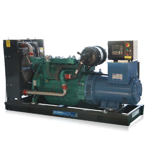
The four failures above share a root cause: a design that counted components without checking paths. The corrective pattern is consistent.
Individual Generators to a Common Bus, Not Pairs
This is the single highest-value change available, and it costs almost nothing at design stage. Each generator connects individually to a common bus in the paralleling gear, with its own breaker and its own protection. The fleet then behaves the way the N+1 arithmetic assumed: one failure, one generator lost. If the plant is already built with paired connections, the correction is a switchgear project rather than a generator project.
Independent Distribution Paths and Dual-Corded Load
Redundancy in the generation layer only pays if the distribution below it can use it. That means at least two independent paths from the generator bus to the load, and a load that is dual-corded so it can accept both.
A single-corded load, no matter how much generation sits behind it, has a single path and therefore a single point.
Generator, UPS and Switchgear Redundancy as One Problem
The most useful reframe is to stop treating generation, UPS and switchgear as three separate redundancy calculations. They are one system, and its redundancy is set by the weakest layer.
A generator fleet with a common switchboard and a single ATS is not an N+1 plant. A 2N UPS system fed from a single generator bus is not a 2N power chain. The question to ask is not “how many of each do we have” but “trace any single path from utility to server, and does the site survive losing it.” Our guide to UPS backup power covers the uninterruptible side of that chain and how it interfaces with the generator fleet. The N+1 UPS and generator plant have to be designed together, and colocation backup power design usually starts from the dual-corded load rather than the generator count.
Where the fleet runs on natural gas rather than diesel, the same topology questions apply, though fuel supply arrangements add constraints of their own. Our natural gas generator guide for data centers covers the fuel side.
Proving It: Commissioning and Load Bank Testing
An N+1 design is an intention until it is tested, and the tests that matter are the ones that remove things.
A useful commissioning sequence does more than start the generators and confirm they accept load. It exercises the failure modes the redundancy was bought for:
- Loss of the largest single generator under load, with the remaining units observed for overload, frequency dip and recovery.
- Loss of each transfer path, confirming the load transfers and the alternate path picks up cleanly.
- Loss of the utility during generator operation, and recovery back to the utility.
- Loss of a control component inside the paralleling gear, which is the test most plants skip.
- Block loading the full critical load onto the generator bus, which is what happens in a real outage and rarely in a commissioning script.
An illustrative composite: a commissioning engineer in northern Europe spent a week on a site whose N+1 plant had passed every functional test on the schedule. It then failed a control-component loss test on the paralleling gear. Removing a single controller dropped the fleet to one machine, and the redundancy present in the hardware the whole time turned out to be unavailable in practice. Our generator load bank testing procedure sets out the test sequence we recommend for fleet installations.
A second discipline is to write down what the site loses for every component on the single line. If any line reads “site down,” you have found a single point, whether or not the generator count says N+1.
Frequently Asked Questions
Does N+1 generator redundancy make a data center Tier III?
No. Uptime Institute defines Tier III by concurrent maintainability, not by generator count. N+1 is one way to get there, but the plant also needs distribution paths and switchgear that can be maintained under load.
How does N+1 vs 2N redundancy compare for a server farm?
N+1 means one generator beyond the number needed to carry the load, inside a single plant. 2N means two complete and independent power systems, each capable of carrying the full load on its own. 2N removes more single points and costs considerably more.
Is redundancy the same as fault tolerance?
No. Redundancy means a spare exists. Fault tolerance means the spare is already wired, energised and carrying its share on an independent path, so a failure is absorbed without any transfer step.
Can one breaker defeat an N+1 plant?
Yes, if the generators are connected in pairs behind shared breakers. A single shared breaker trip removes two generators at once, which is more than the plant was designed to lose.
How is N+1 redundancy tested?
By removing things while the site is on generator. The core tests are loss of the largest generator under load, each transfer path, a paralleling-gear control component, and a full block-load test onto the generator bus.
Does NFPA 110 specify how much fuel a Tier III site needs?
NFPA 110 sets a floor rather than a tier rule. Level 1 systems are expected to start and accept load within 10 seconds, against 60 seconds for Level 2. How long the site can then run is a project decision, not a Uptime Institute requirement tied to a tier.
Conclusion: N+1 Generator Redundancy for Server Farms Is a Wiring Question
N+1 generator redundancy for server farms is a capacity relationship, and it is only as good as the paths beneath it.
The plant that fails is rarely the one that was sized wrong. It is the one that was sized correctly, counted its generators, and never traced the failure paths. A shared breaker that trips, a switchboard that needs cleaning, a controller in the paralleling gear that goes dark: each of those defeats the count. Every one is a wiring question, and every one is cheapest to answer on the drawing.
Three things are worth taking away. Buy the property the tier names rather than the class name, because concurrent maintainability and fault tolerance are properties and N+1 is only one route to them. Treat generation, UPS and switchgear as one system, because the weakest layer sets the redundancy of the whole chain. Test by removal rather than by confirmation, and record what the site loses for every component on the single line.
Reviewing a redundancy design, or specifying a fleet? Send our engineering team your single-line diagram, generator schedule and load profile, and we will flag the points where the plan loses its spare. Contact ZC Power to arrange that review.